Ultrasonic diagnosing system

a diagnostic system and ultrasonic technology, applied in the field of ultrasonic diagnostic equipment, can solve the problems of difficult to clarify the scanning part of the luminal portion, the first problem is not solved in real-time during the examination, and the spread of the lesion along the luminal portion

Active Publication Date: 2005-10-13
OLYMPUS CORP
View PDF14 Cites 24 Cited by
  • Summary
  • Abstract
  • Description
  • Claims
  • Application Information

AI Technical Summary

Problems solved by technology

Consequently, the apparatus disclosed in Japanese Unexamined Patent Application Publication No. 11-113913 has the following problems.
First problem: it is hard to clarify how the lesion is spreading along the luminal portion.
Second problem: it is hard to clarify which part in the luminal portion is scanning during the examination.
However, the apparatuses disclosed in Japanese Unexamined Patent Application Publication Nos. 11-318884 and 2000-243766 have a drawback that the first problem is not solved in real-time during the examination.
Further, the apparatuses disclosed in Japanese Unexamined Patent Application Publication Nos. 11-318884 and 2000-243766 have a drawback that the second problem such that it is hard to clarify which part in the luminal portion is scanning during the examination (particularly, during the scanning) is still unsolved.
However, in the apparatuses disclosed in Japanese Unexamined Patent Application Publication Nos. 11-318884 and 2000-243766, the first and second problems are not solved during the examination, therefore, the recording of the necessary image is not clearly recognized, and the advantage to easily express the tomographic image is not obtained.

Method used


Image

  • Ultrasonic diagnosing system
  • Ultrasonic diagnosing system
  • Ultrasonic diagnosing system

Examples


first embodiment

[0021] Hereinbelow, a description is given of the structure and the operation of an ultrasonic diagnostic apparatus according to the first embodiment with reference to FIGS. 1 to 10.

[0022] (Structure)

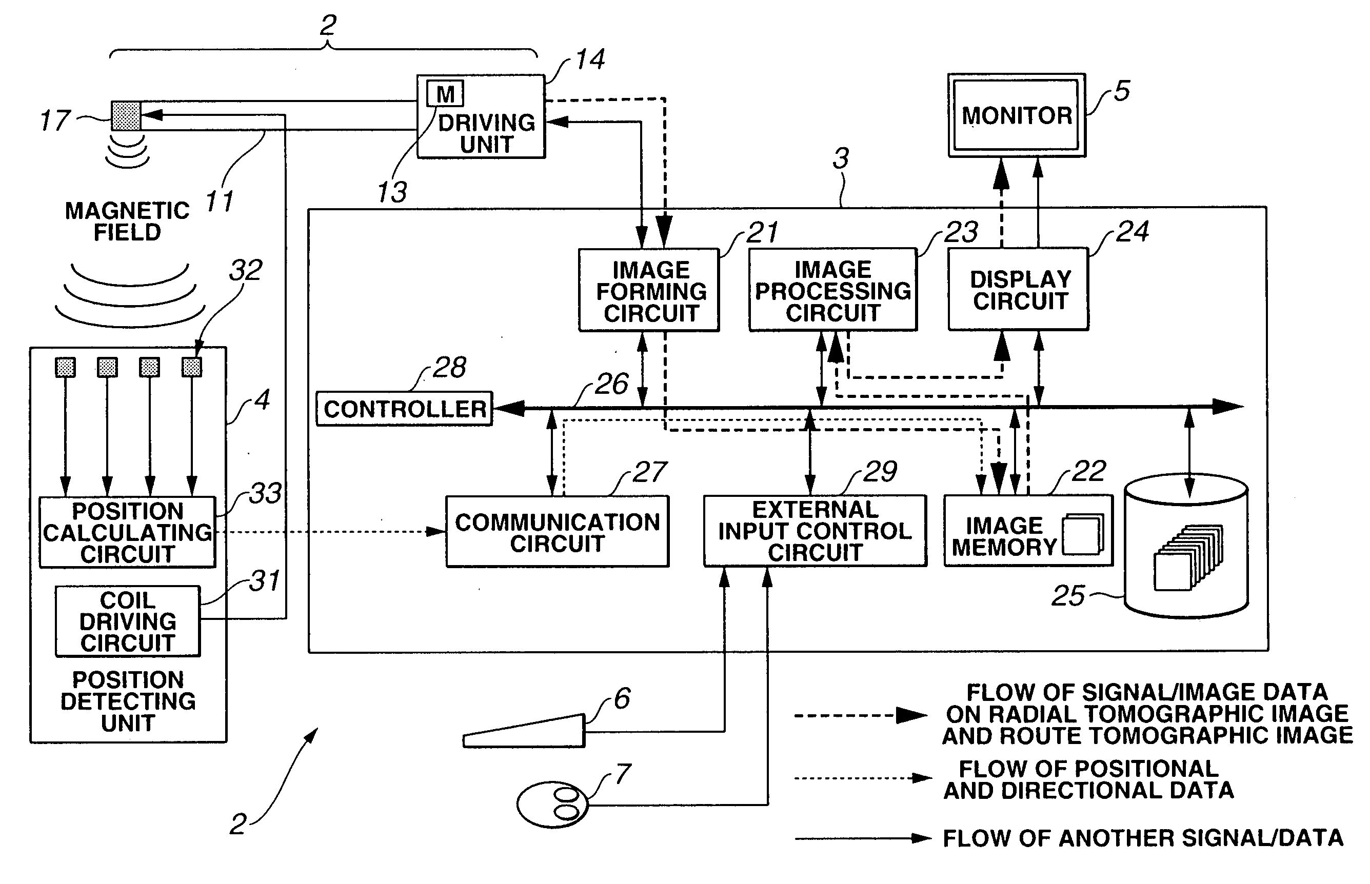
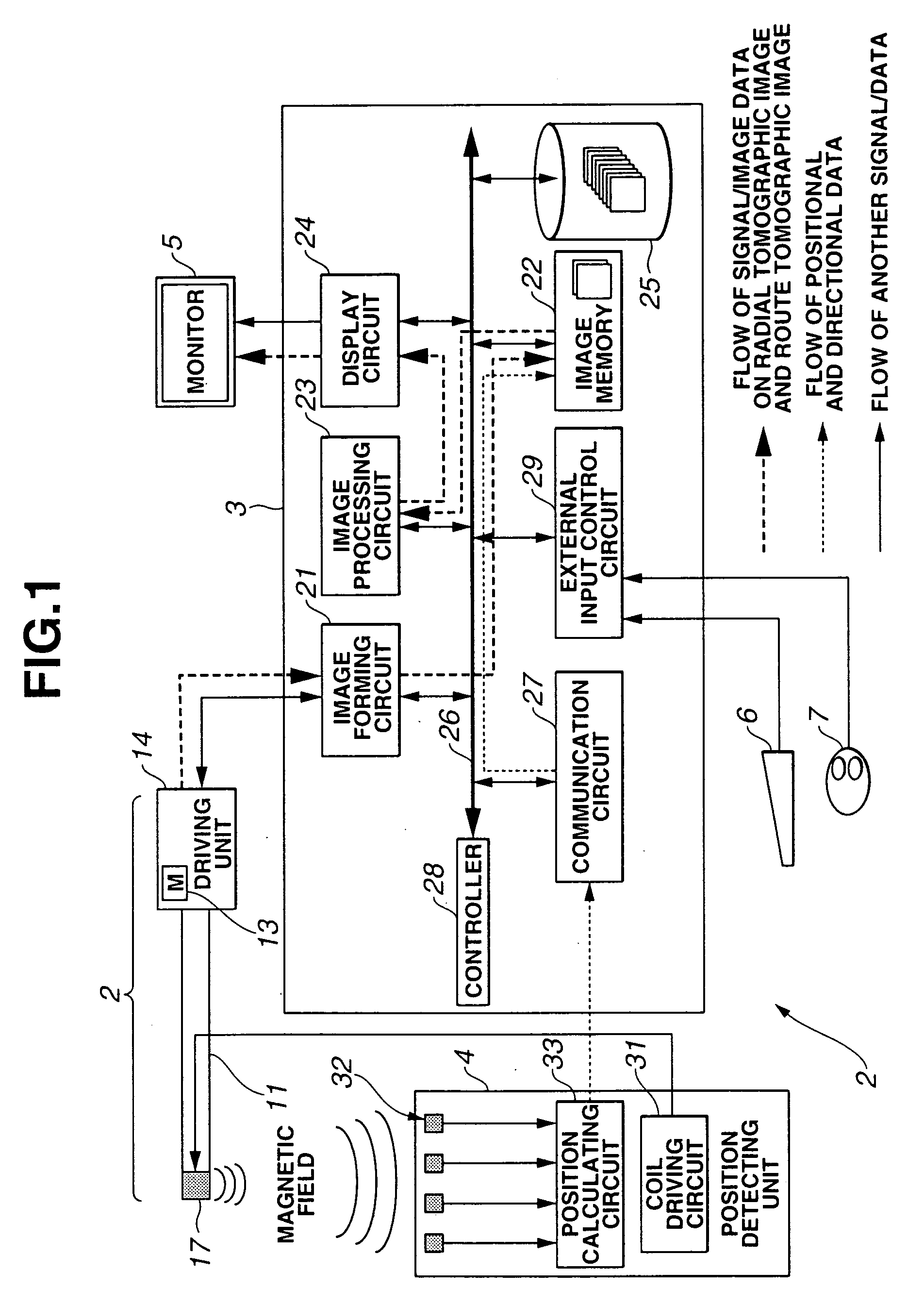
[0023] Referring to FIG. 1, an ultrasonic diagnostic apparatus 1 according to the first embodiment comprises an ultrasonic endoscope 2, an ultrasonic observing portion 3, a position detecting unit 4, a monitor 5, a keyboard 6, and a mouse 7.

[0024] The ultrasonic endoscope 2 has an inserting portion 11 which is inserted in the body cavity of a subject, containing a flexible material, and a driving unit 14 having a motor 13 for driving an ultrasonic vibrator (which will be described later) of the inserting portion edge.

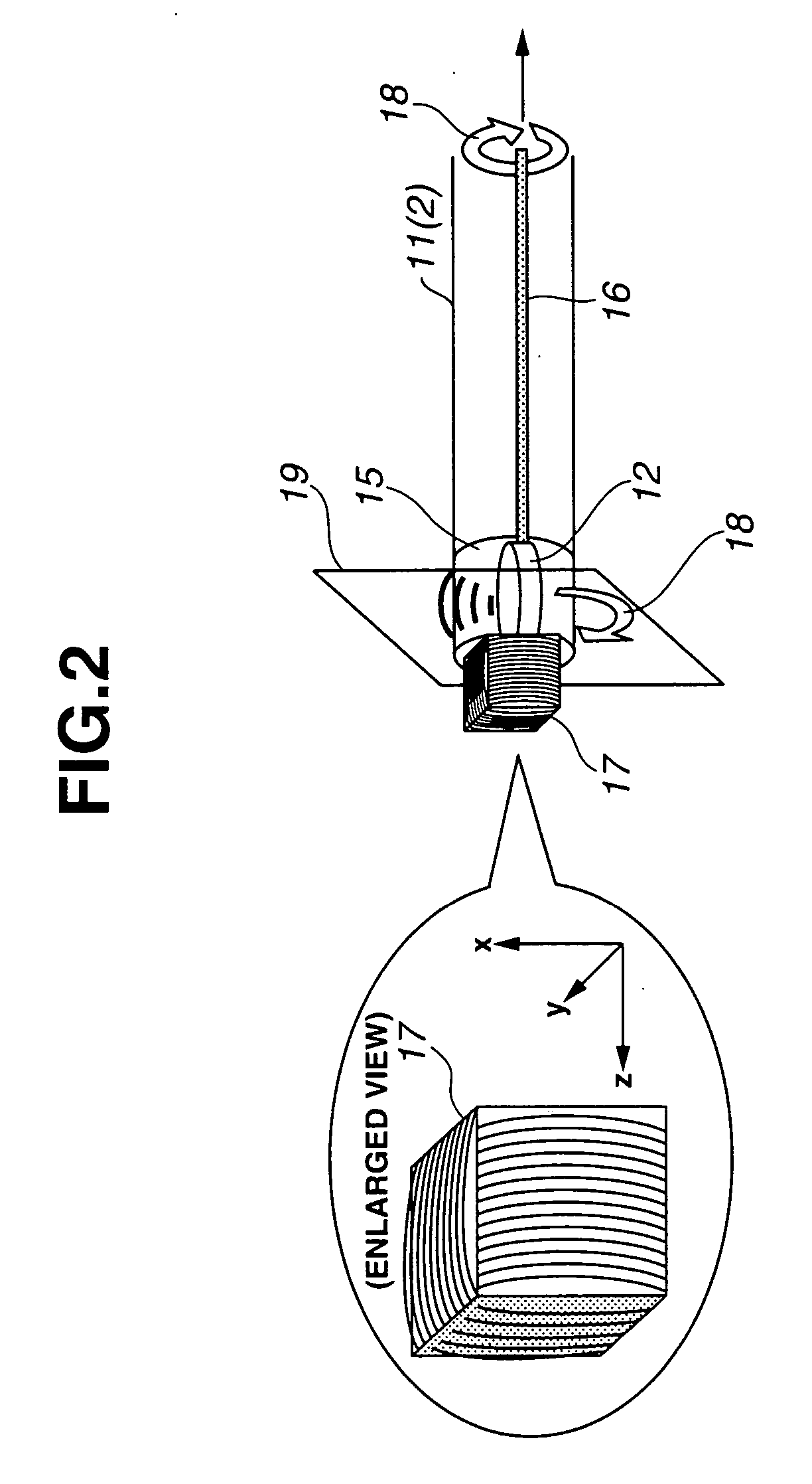
[0025] The state of the edge of the inserting portion 11 will be described with reference to FIG. 2. Referring to FIG. 2, the inserting portion 11 has, at the edge thereof, an acoustic transparent edge cap 15 which is made of a material for transmitting ultrasonic waves...

second embodiment

[0107] The second embodiment is almost the same as the first embodiment, therefore, only different points are described, the same reference numerals denote the same components, and a description thereof is omitted.

[0108] Hereinbelow, a description is given of the structure and the operation of the ultrasonic diagnostic apparatus according to the second embodiment with reference to FIGS. 11 and 12.

[0109] (Structure)

[0110] Referring to FIG. 11, the driving unit 14 according to the second embodiment does not have the motor. However, referring to FIG. 12, the ultrasonic vibrator is cut in rectangles at the edge of the inserting portion in an ultrasonic endoscope 2a according to the second embodiment and thus a circular array (hereinafter, referred to as an ultrasonic vibrator array) 51 is aligned around the inserting axis. Ultrasonic vibrators forming the ultrasonic vibrator array 51 are connected to the image forming circuit 21 in the ultrasonic observing unit 3 via the signal lines...

third embodiment

[0122] The third embodiment is substantially the same as the first embodiment, therefore, only different points are described, the same reference numerals denotes the same components, and a description thereof is omitted.

[0123] (Structure and Operation)

[0124] Hereinbelow, the structure and the operation of an ultrasonic diagnostic apparatus will be described according to the third embodiment with reference to FIG. 13. The entire structural diagram is the same as FIG. 11.

[0125] Referring to FIG. 13, a radial scanning ultrasonic probe according to the third embodiment uses a capsule ultrasonic endoscope (hereinafter, referred to as the capsule ultrasonic endoscope) 101 as the radial scanning ultrasonic probe.

[0126] The capsule ultrasonic endoscope 101 comprises the transmitting coil 17, the ultrasonic vibrator 12, a rigid shaft 104, an ultracompact motor 102, and a signal cable 103. Unlike the first embodiment, the driving unit 14 does not have the motor 13. In place of the motor ...


PUM


Abstract

An ultrasonic diagnostic apparatus has an ultrasonic endoscope, an ultrasonic observing portion, a position detecting unit, a monitor, a keyboard, and a mouse. Cross-sectional planes in parallel therewith are set to radial tomographic images, an intersecting line segment is obtained between a radial tomographic image and the cross-sectional plane, the intersecting line segments are combined, and a route tomographic image is generated. It is easily recognized how the lesion is spreading along the luminal portion during the examination by advancing and returning a radial scanning ultrasonic probe. Further, which part in the luminal portion is scanning during the examination can easily be recognized during the examination.

Description

TECHNICAL FIELD [0001] The present invention relates to an ultrasonic diagnostic apparatus which generates a plurality of time-series radial tomographic images in the advancing and returning operation of a radial scanning ultrasonic vibrator in the body cavity of a subject. BACKGROUND ART [0002] Japanese Unexamined Patent Application Publication No. 11-113913 discloses an ultrasonic diagnostic apparatus which has a position detector at the edge thereof and easily obtains spatial ultrasonic image data along a route by advancing and returning a general radial scanning ultrasonic probe (including an ultrasonic endoscope with an optical observing window) along a bent or inflected luminal portion so as to obtain a plurality of ultrasonic tomographic images. Various expressing methods of the spatial ultrasonic image data are examined and Japanese Unexamined Patent Application Publication No. 11-113913 discloses the expressing method with an ultrasonic three-dimensional image or a pluralit...

Claims


Application Information

Patent Timeline
Patent Type & Authority Applications(United States)
IPC IPC(8): A61B8/12A61B8/14G01S7/52G01S15/89G06T1/00
CPCA61B8/12A61B8/14A61B8/145A61B8/4254G01S15/8997A61B8/483A61B8/523G01S7/52065G01S7/52074A61B8/463
Inventor KAWASHIMA, TOMONAO
Owner OLYMPUS CORP
Why Eureka
Try Eureka