Load distribution crown

a technology of loading crown and crown sleeve, which is applied in the field of loading crown, can solve the problems of free end movement of the crown, and achieve the effect of reducing the chance of undetected bone structural integrity damag

Active Publication Date: 2005-10-13
GLOBUS MEDICAL INC
View PDF21 Cites 26 Cited by
  • Summary
  • Abstract
  • Description
  • Claims
  • Application Information

AI Technical Summary

Benefits of technology

[0008] The present invention relates to a crown that distributes the load of a fastening device in order to reduce the chances of the structural integrity of the bone being undesirably compromised. The present invention may be used with any type of fastening devices, such as screws, nails, or the like that have any desired physical characteristics. The fastening device is preferably inserted through an opening in the load distribution crown. Preferably, both the fastening device and the crown are configured and dimensioned to have complimentary interfaces. The complimentary interfaces allow the two surfaces to rest flush against one another. One advantage of allowing the two surfaces to be flush is that the load may be more evenly distributed over the bottom surface, or base, of the crown facing the bone in which the fastener is inserted. Another advantage of the complimentary interfaces is that the load may be distributed evenly even when the screw or fastener is inserted at a non-orthogonal angle.
[0009] In one embodiment, the bottom surface of the crown lies substantially flush with the surface of the bone. In another embodiment, the crown is configured to have a slit or cut extending from its outer perimeter edge to the inner perimeter edge that defines the opening through which the fastener is inserted. The cut or opening may be further defined by two free ends of the crown. When a slit or cut is present, one end of the crown that defines the cut or slit may be disposed higher than the opposing end of the crown. As the fastener is inserted through the opening and into the bone, the head of the fastener may apply pressure to the surface of the crown and cause the crown to flex or bend, thereby causing the free ends of the crown to move toward a common plane. In one embodiment, the free ends of the crown may move from about 0.1 mm to about 5 mm before reaching a common plane. In another embodiment, the free ends may move from about 0.5 mm to about 3 mm before reaching a common plane. The flexing of the material that forms the crown allows for the storage of potential energy in the crown that can be released if the screw backs out. In addition, the use of a slit or cut allows for gradual increasing and decreasing of load distribution by the crown as the fastener is inserted into or removed from the bone.
[0015] One advantage of using protrusions is that the screw or fastener may be more likely to stay in place when used in combination with a crown. In addition, the protrusions may help minimize shearing or grinding of the bone during insertion of the screw. In one embodiment of the invention, a portion of the crown and screw have complimentary interfacing surfaces that permit the fastener to rotate or swivel relative to the crown. This allows the bottom surface of the crown to achieve contact with the bone even if the fastener is inserted of angle from an orthogonal direction.
[0021] In another embodiment, the complementary surfaces of the crown and fastener head may be configured with a plurality of ridges, steps, or ledges extending substantially in a direction orthogonal to the rotational direction of the fastener. As the ridged surfaces of the fastener and crown begin to engage, and ultimately reach their final position, the ridges may help resist forces from micromotion or vibration that might cause the fastener to back out of its position.
[0022] In order to effectively distribute the load caused by the fastener, the total surface area of the base of the crown may be about 10 square mm or greater. In some embodiments, it may be desirable to deform the surface area of the base in order to match the contour of the base to the contour of the bone involved. In such embodiments, the force necessary to deform the crown is preferably substantially greater than the force necessary to insert the screw into the bony tissue. For instance, the force needed to bend or deform the crown may be about 5 times or greater than forces that may be imparted on the crown by the fastener during insertion into bone. This prevents the crown from being deformed during the insertion of the screw. In some embodiments, an incision, cut, or slot may be formed in either the top or base to aid in deforming the crown at one or more predetermined locations.
[0023] It is desirable to prevent the fastener from passing completely through the crown. This may be achieved by making the diameter of the crown opening, through which a threaded portion of a screw or body portion of a fastener may pass, at least between about 5% and 10% smaller than the diameter of the head of the fastener. To permit rotation or swiveling of the fastener relative to the crown, the diameter of the fastener may be from about 5% to about 30% less than the diameter of the diameter of the crown opening.

Problems solved by technology

As the fastener is inserted through the opening and into the bone, the head of the fastener may apply pressure to the surface of the crown and cause the crown to flex or bend, thereby causing the free ends of the crown to move toward a common plane.

Method used


Image

  • Load distribution crown
  • Load distribution crown
  • Load distribution crown

Examples


Embodiment Construction

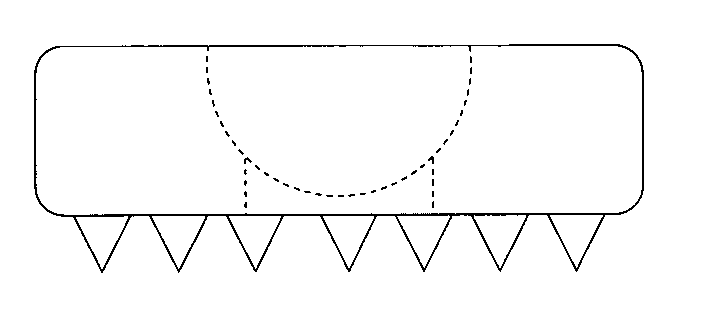
[0034] Fastening devices are currently used in a wide variety of applications that range from construction to medical equipment. Typical fastening devices include nails and screws. Screws are often used as fastening devices in medical applications, typically to fasten a device to bony tissue or to provide temporary or permanent support.

[0035] In medical applications, one consideration when using a screw is the amount of force that the screw will exert on the bony tissue that it is inserted into. If a screw exerts too much pressure on bony tissue, it can compromise the structural integrity of the bone, which can cause many complications. The angle of insertion can also compromise the structural integrity of the bone. In some instances if the angle of insertion diverges significantly from a direction orthogonal to the bone it may cause the bone to crack or break. Thus, the angle of insertion and the pressure that a screw exerts are factors to consider when used in medical application...


PUM


Abstract

An apparatus for distributing the load caused by the insertion of a fastening device into bony tissue is disclosed. In one embodiment, the apparatus comprises a crown having a plurality of protrusions. The protrusions may have any desired physical properties, and function to obtain purchase in the bony tissue. Preferably, the crown includes an opening that is selectively engageable with a spherical head of the fastening device. The opening preferably comprises a spherical curvature that allows the surfaces of the spherical head and the opening to maintain flush contact, even when the fastening device is inserted into the bony tissue at a non-orthogonal angle. When the fastening device is inserted into the bony tissue, the crown distributes the load over a wider section of the bone, allowing the bone to maintain its structural integrity.

Description

FIELD OF THE INVENTION [0001] The present invention relates to fastening devices used with bony tissue. More specifically, the present invention relates to an apparatus that distributes the load of a fastening device in order to prevent the structural integrity of the bony tissue from being compromised. BACKGROUND OF THE INVENTION [0002] The field of medical engineering is rapidly expanding due to advances in engineering, material science, and advances in the field of medicine. These advances have allowed doctors and engineers to work together to create instruments and devices that allow more accurate and effective diagnosis and treatment of a wide variety of ailments. The diagnoses and treatments enable patients to recover from injuries or diseases that used to be crippling, or even fatal. [0003] One area of the human body that is of particular importance is the skeletal system. Advances in medical engineering and medicine have allowed doctors to treat a wide variety of ailments in...

Claims


Application Information

Patent Timeline
Patent Type & Authority Applications(United States)
IPC IPC(8): A61B17/56A61B17/86
CPCA61B17/8695A61B17/86
Inventor PAUL, DAVID C.
Owner GLOBUS MEDICAL INC
Why Eureka
Try Eureka