Double lead bone screw

Inactive Publication Date: 2005-10-13
DEPUY SPINE SARL
View PDF18 Cites 51 Cited by
  • Summary
  • Abstract
  • Description
  • Claims
  • Application Information

AI Technical Summary

Benefits of technology

[0008] In yet another embodiment of the present invention, a bone screw is provided having a head with a driver-receiving element formed thereon, and a shank formed from first and second axially symmetrical threads offset approximately 180° from one another and extending around the shank between proximal and distal ends thereof. The threads preferably have a depth that remains substanti

Problems solved by technology

Conventional bone screws, however, typically require a relatively large core diameter to withstand high torque without shearing or otherwise failing.
A thick core can, however, displace enough bone to cause

Method used


Image

  • Double lead bone screw
  • Double lead bone screw
  • Double lead bone screw

Examples


Embodiment Construction

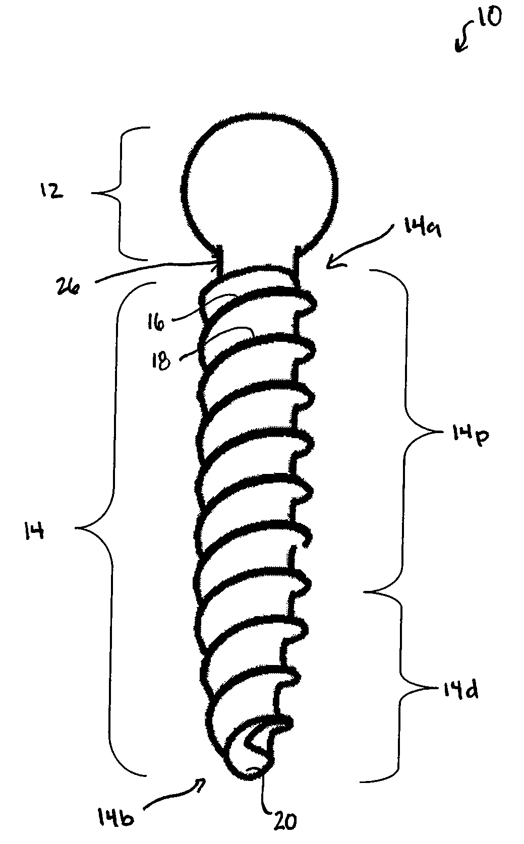
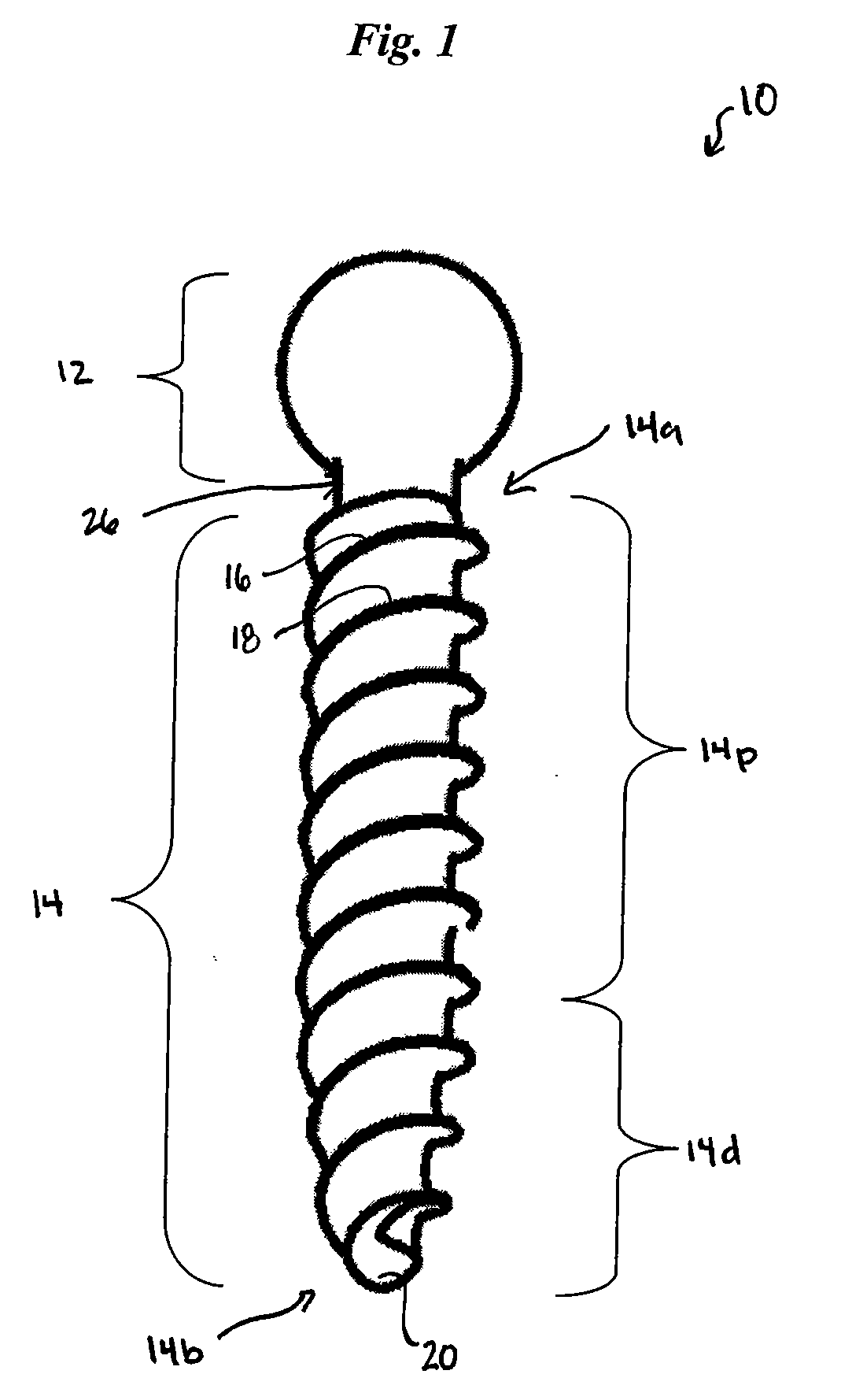
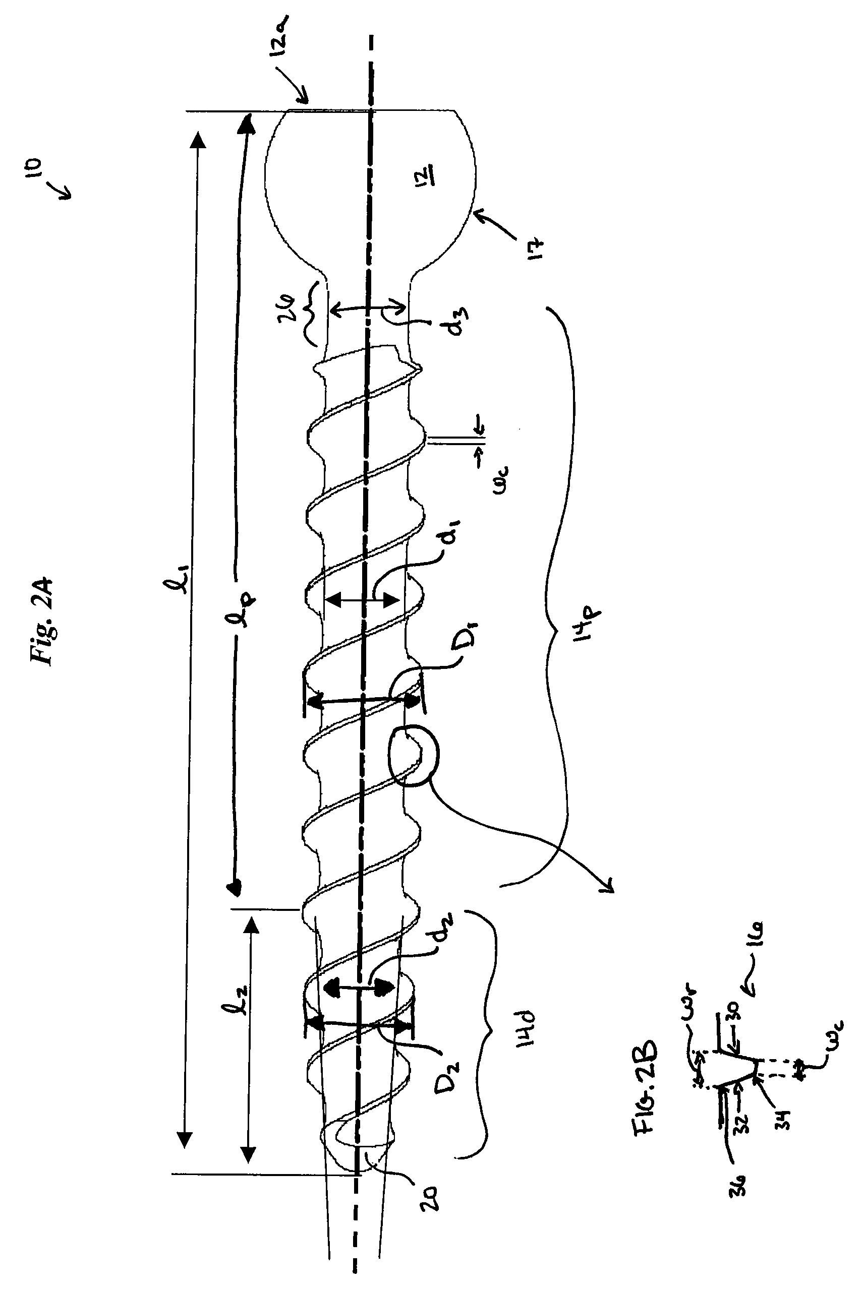
[0014] In general, as shown in FIGS. 1-3, the present invention provides a bone screw 10 having a head 12 that can be adapted to mate with a driver tool, and a shank 14 having proximal and distal ends 14a, 14b. First and second helical threads 16, 18 extend around the shank 14 between the proximal and distal ends 14a, 14b thereof, and the threads 16, 18 are axially symmetrical and offset approximately 180° from one another. The shank 14 also includes proximal and distal portions 14p, 14d that differ from one another, and that are particularly adapted to facilitate use of the bone screw 14 in a patient's spinal column. In particular, the proximal and distal portions 14p, 14d are configured to facilitate relatively quick and easy insertion of the bone screw 10 into bone, and to provide adequate fixation once implanted.

[0015] The head 12 of the bone screw 10 can have a variety of configurations, and it can be adapted for a variety of uses. As shown in FIGS. 2A-3, the head 12 of the bo...


PUM


Abstract

A bone screw is provided having a head and a shank with opposed first and second helical threads extending there around. In one embodiment, the shank has a proximal portion with a constant minor diameter, and a distal portion with a minor diameter that decreases in a proximal-to-distal direction to form a taper. The opposed first and second helical threads preferably define a thread depth that remains constant along the length of the shank. In an exemplary embodiment, a major diameter of the shank at a distal tip of the shank is equal to or less than the minor diameter of the proximal portion of the shank.

Description

FIELD OF THE INVENTION [0001] The present invention relates to bone screws, and in particular, to a bone screw having improved physical and mechanical properties. BACKGROUND OF THE INVENTION [0002] Bone screws are used for a variety of medical purposes, including to correct spinal pathologies, deformities, and trauma. Spinal bone screws are loaded with axial, distractive, and compressive forces, and with subsequent cyclically loaded forces applied through the patient's natural movement. Thus, spinal bone screws must be sufficiently strong, while at the same time they must be designed to minimize potential damage to the bone. [0003] Conventional bone screws are typically made from a cylindrical or tapered core having a helical thread with either a variable or a constant major diameter extending along the entire length of the screw. The helical shape of the threads cuts a path into the bone as the screw rotates, and prevents the screw from being axially pulled out of the bone. Thus, t...

Claims


Application Information

Patent Timeline
IPC IPC(8): A61B17/58A61B17/86
CPCA61B17/863
Inventor BRODKE, DARRELKUMAR, G. KRISVARIEUR, MICHAEL
Owner DEPUY SPINE SARL
Why Eureka
Try Eureka