Anti-adhesive surface treatments

a technology of anti-adhesion and surface treatment, which is applied in the field of surface treatment, can solve the problems of difficult to obtain the desired mechanical properties and desired chemical properties in the same material, the difficulty of contacting biomaterials suitable for long-term implantation, and the concomitant risks, so as to reduce the adhesion to bacteria

a technology of anti-adhesion and surface treatment, which is applied in the field of surface treatment, can solve the problems of difficult to obtain the desired mechanical properties and desired chemical properties in the same material, the difficulty of contacting biomaterials suitable for long-term implantation, and the concomitant risks, so as to reduce the adhesion to bacteria

US20050228491A1Inactive Publication Date: 2005-10-13PENN STATE RES FOUND

Image

  • Anti-adhesive surface treatments
  • Anti-adhesive surface treatments
  • Anti-adhesive surface treatments

Examples


Embodiment Construction

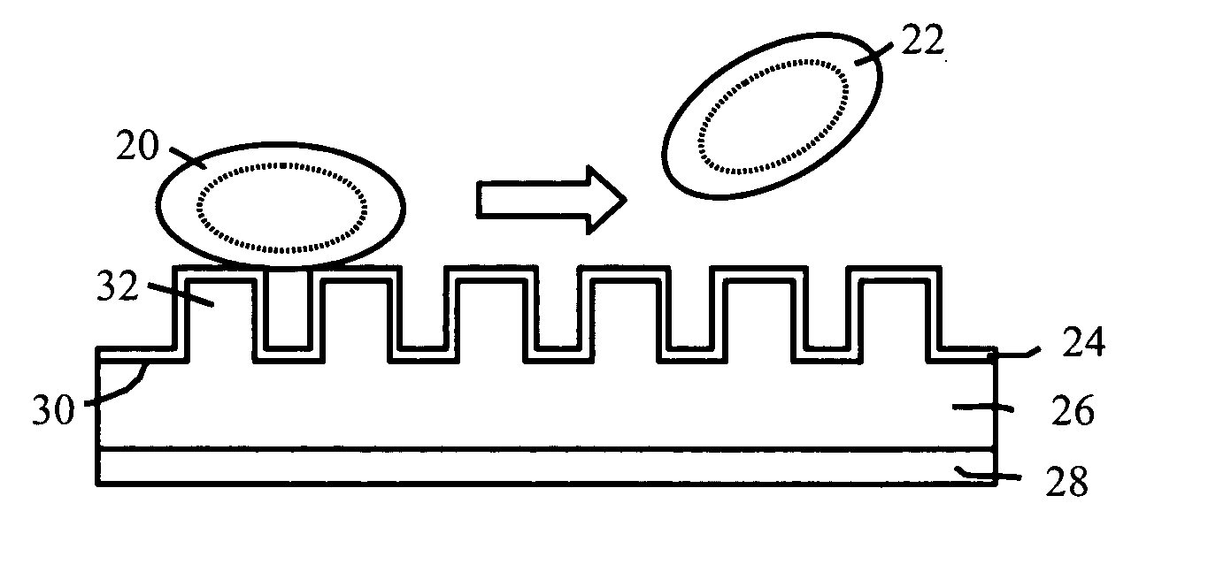
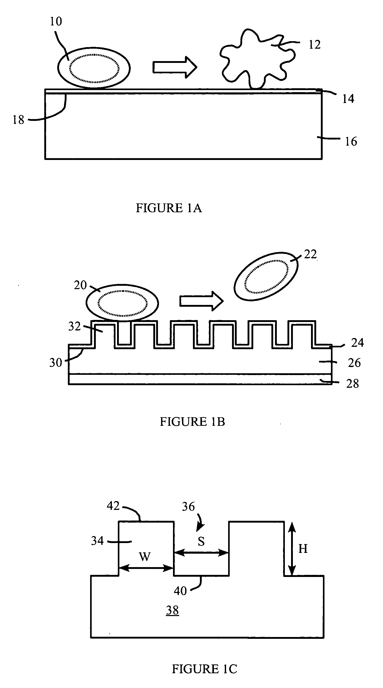
[0023] Adhesion of formed elements to a surface is dependent on the formed elements accessing the material surface. Biological formed elements such as platelets and bacteria may access the surface through mediating adhesion molecules and / or molecules which coat the synthetic surface. An example surface having reduced adhesion to formed elements comprises topographic features that reduce the surface area available for adhesion. The topographic features may include protrusions, extending generally away from the bulk of the material, such as ridges, pillars, and the like. The topographic features may also comprise indentations, such as pits, troughs, and the like.

[0024] Adhesion of biological formed elements such as cells, platelets, and the like to surfaces can cause problems in many situations. For example, adhesion of platelets to surfaces may lead to thrombosis, as discussed in more detail below. Examples discussed in this specification sometimes are directed towards platelets as ...


PUM

PropertyMeasurementUnit
heightaaaaaaaaaa
heightaaaaaaaaaa
widthaaaaaaaaaa

Abstract

A surface providing reduced adhesion to formed elements, having an element dimension such as formed element diameter, has a plurality of topographic features. The topographic features have a feature dimension less than the dimension of the formed element so as to reduce the accessible area of the surface available to the formed element for adhesion to the surface. The topographic features may include protrusions, such as pillars.

Description

REFERENCE TO RELATED APPLICATION [0001] This application claims priority to U.S. Provisional Patent Application Ser. No. 60 / 561,350, filed Apr. 12, 2004, the entire content of which is incorporated herein by reference.FIELD OF THE INVENTION [0002] The present invention relates to surfaces providing reduce adhesion of formed elements, such as biological formed elements, to a surface. In particular, the invention relates to methods and apparatus to reduce the adhesion of biological formed elements such as platelets to surfaces in contact with biological fluids such as blood. BACKGROUND OF THE INVENTION [0003] Many formed elements, such as cells and platelets, can adhere effectively to smooth surfaces, whether they are flat or gently curved, and may also adhere or reside preferentially in grooves, wells or crevices that are somewhat larger than the formed elements. Such structures may present a large surface area with which the formed element may interact and may further shield the for...

Claims


Application Information

Patent Timeline
13 Oct 2005
Publication
US20050228491A1
IPC
A61F2/00; A61F2/02; A61F2/06; B29C33/40
CPC
A61F2/06; B29C33/405; A61F2002/009; A61F2/0077
Inventors
SNYDER, ALAN J.; SIEDLECKI, CHRISTOPHER A.