Storage device

Active Publication Date: 2005-10-13
GOOGLE LLC
View PDF13 Cites 66 Cited by
  • Summary
  • Abstract
  • Description
  • Claims
  • Application Information

AI Technical Summary

Problems solved by technology

However, in this conventional technique, the time is shortened only on the server side; no consideration is given to shortening the time on the side of the storage device.
Accordingly, even if an attempt is made to shorten the failover time on the server side, the failover time cannot be shortened unless the response characteristics of the storage device are improved.
The reason for this is that the response characteristics of the storage device during failover constitute a bottleneck.
Since systems in which a high-performance, high-ca

Method used


Image

  • Storage device
  • Storage device
  • Storage device

Examples


first embodiment

1. First Embodiment

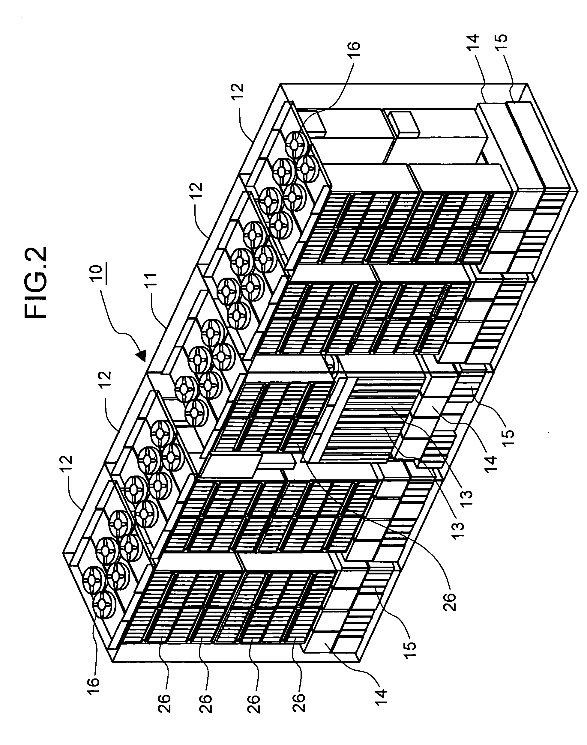
[0055]FIG. 2 is a schematic perspective view which shows the external appearance and construction of a storage device 10. For example, this storage device 10 can be constructed from a basic housing 11 and a plurality of additional housings 12.

[0056] The basic housing 11 is the minimum constituent unit of the storage device 10, and has both a memory function and a control function. The additional housing 12 are options for the storage device 10, and are controlled by the control function of the basic housing 11. For example, a maximum of four additional housing 12 can be connected to the basic housing 11.

[0057] A plurality of control packages 13, a plurality of power supply units 14, a plurality of battery units 15 and a plurality of disk drives 26 are respectively disposed in a detachable manner in the basic housing 11. A plurality of disk drives 26, a plurality of power supply units 14 and a plurality of battery units 15 are respectively disposed in a detachabl...

second embodiment

2. Second Embodiment

[0152] A second embodiment will be described with reference to FIGS. 15 and 16. This embodiment has the status of a modification of the first embodiment. The characterizing feature of the present embodiment is that even in cases where a status (operating pattern) that is not registered in the management table is detected, the quantity of input-output requests from the servers and the like are taken into account, and the priority rankings are varies in steps.

[0153] In the present embodiment, a case is indicated in which the operating pattern PB1 is detected under conditions in which this operating pattern PB1 is not registered in the cluster management table TA2. At time T41, the business application 111 of the server 110 is stopped in a planned stop (S81). The server 110 releases the exclusive use of the shared logical devices 261 by issuing a release command (S82).

[0154] When the storage device 200 receives the release command from the server 110 (S83), the st...

third embodiment

3. Third Embodiment

[0166] A third embodiment will be described with reference to FIGS. 17 through 20. This embodiment has the status of a modification of the first embodiment. The characterizing feature of this embodiment is that the priority rankings are dynamically altered in accordance with the load states of the respective servers and the operating patterns at the time that failover occurs.

[0167]FIG. 17 is a block diagram which shows an overall outline of the storage system. The failover detection part 221 of the present embodiment not only detects failover within the failover cluster, but also detects whether or not the respective servers 110 through 140 are in an overload state. The management table 243 comprises substantially the same construction as the management table 242. However, as is shown in FIG. 18, flags which indicate whether or not the priority ranking during overload and the overload state are currently being handled are included in the server management table T...


PUM


Abstract

The present invention observes the status on the server side from the storage device side, and controls the processing priority in accordance with the server status. The storage device 2 is utilized by numerous servers 1A through 1C. The server 1A and server 1B form a failover cluster. The status detection part 5 judges whether or not an event observed from the server 1A or 1B corresponds to a specified event (link down or the like). In cases where such a specified event is observed, the status detection part 5 detects the occurrence of failover. In accordance with the detection of the occurrence of failover, the priority control part 6 sets the processing priority of the failover destination server at a priority that is higher than the ordinary processing priority. When the preset failover time has elapsed, the priority during failover is returned to the ordinary priority.

Description

CROSS-REFERENCE TO RELATED APPLICATIONS [0001] This application relates to and claims priority from Japanese Patent Application No. 2004-113419 filed on Apr. 7, 2004, the entire disclosure of which is incorporated herein by reference. BACKGROUND OF THE INVENTION [0002] 1. Field of the Invention [0003] The present invention relates to a storage device. [0004] 2. Description of the Related Art [0005] Storage devices are also called (for example) disk array devices or the like, and are constructed by disposing numerous disk drives in the form of an array. For example, storage devices provide memory regions on the basis of a RAID (redundant array of independent inexpensive disks). Logical volumes (logical devices) which are logical memory regions are formed on the physical memory regions of each disk drive. For example, a host computer such as a server or the like can read and write desired data by issuing write commands or read commands that have a specified format to the storage devic...

Claims


Application Information

Patent Timeline
IPC IPC(8): G06F13/10G06F3/06G06F11/00G06F11/20G06F12/00
CPCG06F11/2046G06F11/2025
Inventor MORITA, HIDEHIROOKADA, KOICHI
Owner GOOGLE LLC
Why Eureka
Try Eureka