Steel stud with openings and edge formations and method for making such a steel stud

Inactive Publication Date: 2005-10-20
BODNAR ERNEST R
View PDF14 Cites 9 Cited by
  • Summary
  • Abstract
  • Description
  • Claims
  • Application Information

AI Technical Summary

Benefits of technology

[0029] It will be appreciated that a stud which improves on all these problems associated with prior studs, will have application in general use, for many various construction applications. In particular however it will have advantages in the reinforcement of thin-shell concrete panels.
[0030] With a view to achieving the foregoing and other objectives the invention comprises a steel member for use in supporting structures and having reduced heat transfer characteristics as compared with solid web studs, and having a web defining side edges and an axis, a flange on at least one sid

Problems solved by technology

Wood is a relatively poor heat transfer medium.
Metal studs having solid webs however, do create a heat loss transfer path through the wall or other structure.
This results in cold patches along the lines of the studs.
However this did not overcome the heat transfer problem.
It is not possible to the builder to cut away any of the diagonal struts to provide larger openings for services, since this would drastically reduce the strength of the studs.
Another problem arose in that the triangular openings were formed with edge flanges around their perimeter.
Where these edge flanges extended around an angular corner of the opening there was a tendency for the sheet metal to crack.
This meant that there was more metal at each of the corners, than was desirable for heat transfer, and thermal losses could occur.
Another problem arose in cutting these studs to length.
However due to the alternating orientation of the openings, this requirement resulted in cutting off end portions of studs equal in length to the space occupied by two of the stud openings, in many cases.
Concrete panels are usually of relatively heavy thick material of great weight.
Great costs are involved in both materials, labor transportation, and erection of such heavy panels.
Attachment of

Method used


Image

  • Steel stud with openings and edge formations and method for making such a steel stud
  • Steel stud with openings and edge formations and method for making such a steel stud
  • Steel stud with openings and edge formations and method for making such a steel stud

Examples


Example

[0066] As already described the invention provides sheet metal studs, having reduced thermal conductivity, suitable for use in erecting various structures, walls, floors, roofs, and the like. The invention also provides sheet metal studs suitable for use in reinforcement of thin-shell concrete panels which are widely used in completing walls, in particular. Such thin-shell structures can also form floors, roofs and the like. The invention also provides composite members formed by joining two stud portions together, and a method of making such a composite member.

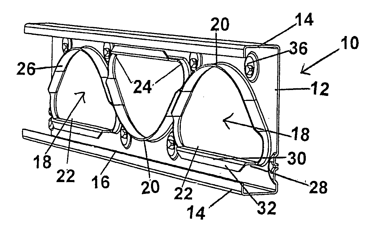
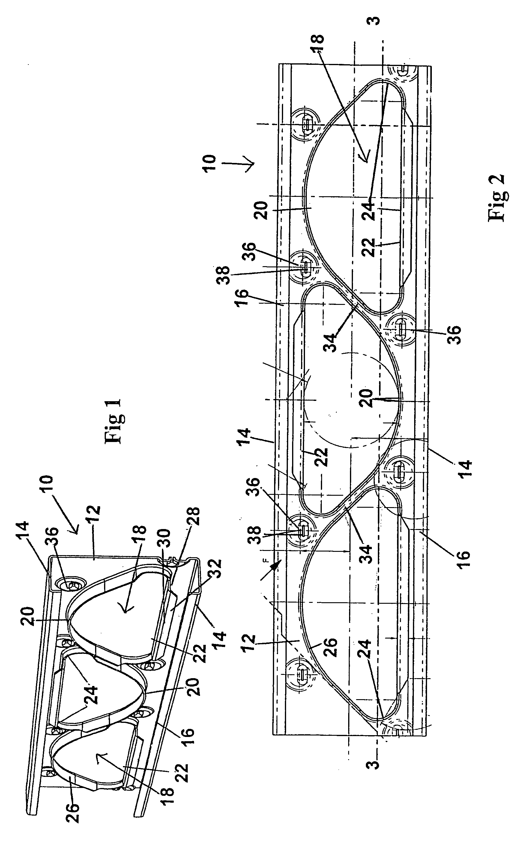
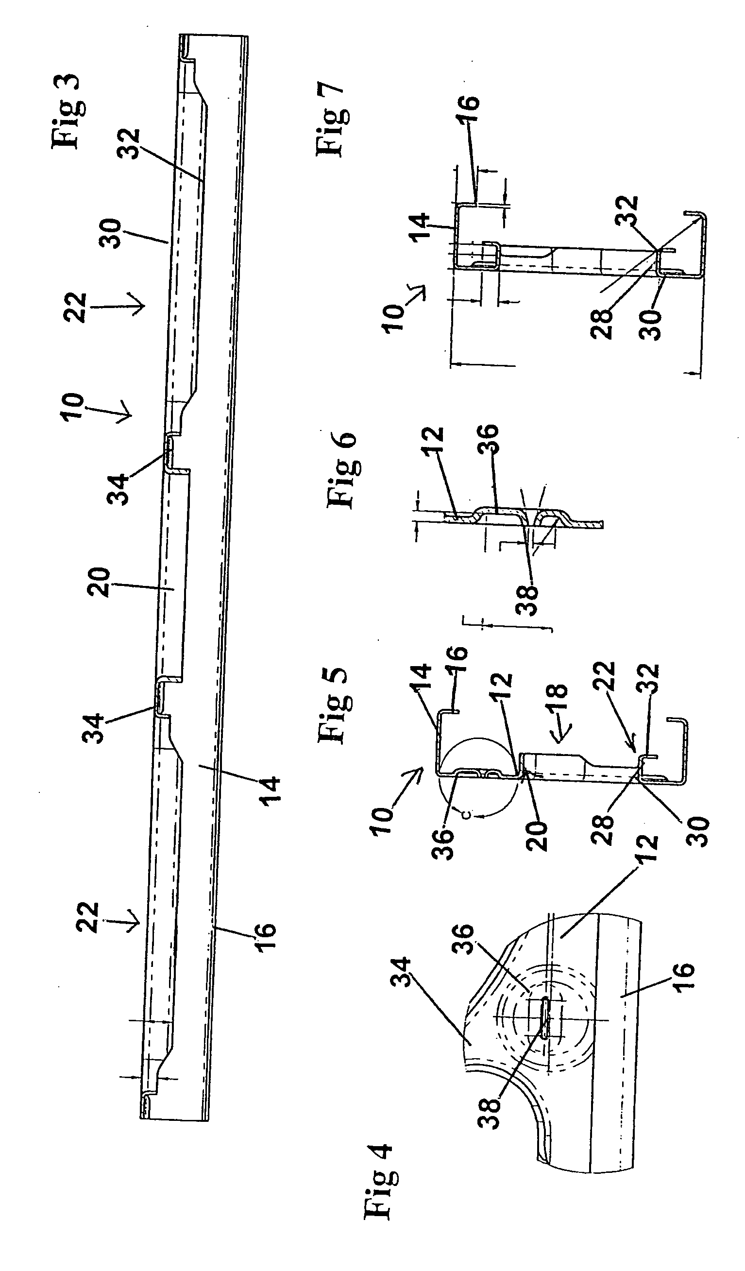
[0067] Referring to FIG. 1 it will be seen that the invention is there illustrated in the form of a stud (10), formed of sheet metal, in this case steel. The stud (10) has a web (12) which is essentially planar, and edge flanges (14) along each side edge of the web (12). Each of the flanges is formed by bending the web at right angles. Lips (16) are formed on each edge flange ( ) again at right angles.

[0068] In the web (12)...


PUM

PropertyMeasurementUnit
Angleaaaaaaaaaa
Flow rateaaaaaaaaaa
Shapeaaaaaaaaaa

Abstract

A steel member (10,40,70,100) for use in supporting structures and having reduced heat transfer characteristics as compared with solid web studs, and having a web (12,42,72,102) defining side edges and an axis, a flange (14,44,74,104) on at least one side edge, openings (18,46,76,112) through said web (12,42,72,102) at spaced intervals therealong, of predetermined size and profile, at least a side portion of said web (12,42,72,102) removed from said opening (18,46,76,112) remaining attached integrally to said web (12,42,72,102), by bend lines being formed along axes parallel to said web axis.
Also disclosed is a composite member (130) made up of two such members (132) joined together.
Also disclosed is a method of making such a member (10,40,70,100,130,132).

Description

FIELD OF THE INVENTION [0001] The invention relates to steel studs or structural members formed with openings, and with edge formations formed around the openings. In particular the studs are formed with edge formations along at least one side of the openings, which are formed with at least two bends at respective first and second angles with respect to the plane of the stud. BACKGROUND OF THE INVENTION [0002] Steel studs of a wide variety have been proposed for erecting structures. Usually such studs are used to replace wooden studs. Wood is a relatively poor heat transfer medium. Heat losses through wooden studs has not been a significant problem in the past. Metal studs having solid webs however, do create a heat loss transfer path through the wall or other structure. This results in cold patches along the lines of the studs. Condensation, known as “ghosting” appears along these lines. [0003] Such studs usually were formed as a C-section, ie there was a central web, and the oppos...

Claims


Application Information

Patent Timeline
IPC IPC(8): E04C3/04E04C3/09
CPCE04C3/09E04C2003/0439Y10T29/49627E04C2003/0473E04C2003/0452
Inventor BODNAR, ERNEST R.
Owner BODNAR ERNEST R
Why Eureka
Try Eureka