
Electrical and electronic component cabinet for a refrigeration compressor

a technology of electronic components and refrigeration systems, which is applied in the direction of domestic cooling devices, positive displacement liquid engines, lighting and heating devices, etc., can solve the problems of limited defects risk after assembly of refrigeration systems, and achieve the effects of reducing assembly time, reducing quality defects, and reducing vibration

Inactive Publication Date: 2005-10-20
DANFOSS COMML COMPRESSORS +1
View PDF14 Cites 1 Cited by
  • Summary
  • Abstract
  • Description
  • Claims
  • Application Information

AI Technical Summary

Benefits of technology

[0014] The opening in the cabinet on the compressor wall enables the compressor wall to be used to cool the cabinet and the electrical and electronic components that it contains.
[0024] Advantageously, the protective cap is made of ABS (acrylonitrile butadiene styrene). ABS (acrylonitrile butadiene styrene) has good mechanical strength and high thermal inertia.

Problems solved by technology

The risks of defects after assembly of the refrigeration system are thus limited.

Method used


Image

  • Electrical and electronic component cabinet for a refrigeration compressor
  • Electrical and electronic component cabinet for a refrigeration compressor
  • Electrical and electronic component cabinet for a refrigeration compressor

Examples


Embodiment Construction

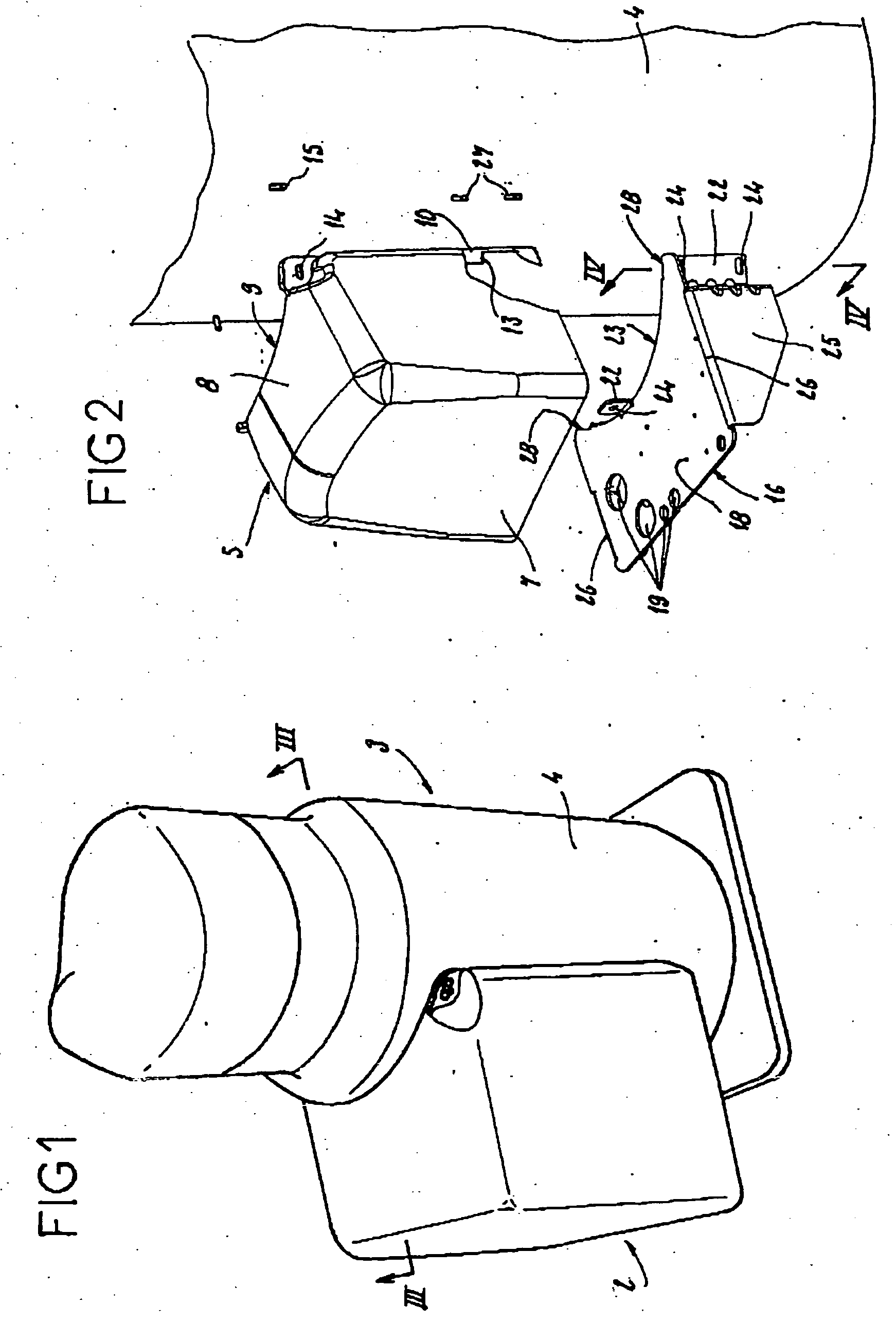
[0030]FIG. 1 shows the cabinet 2 attached to the side wall 4 of a refrigeration compressor 3.

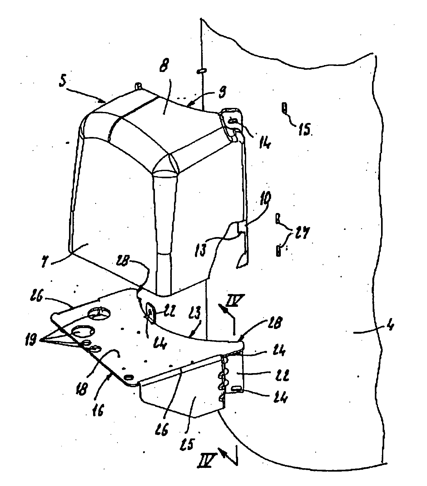
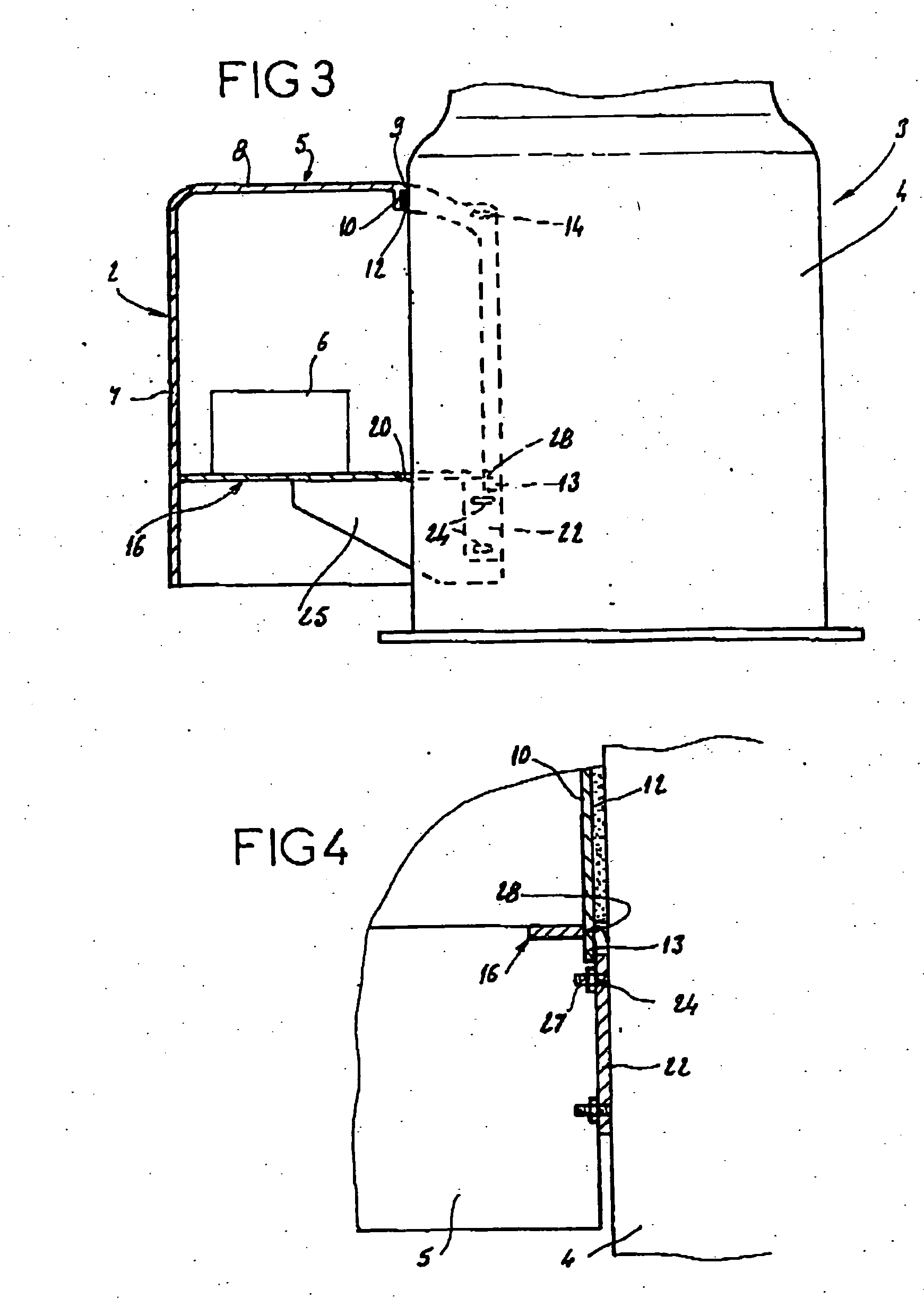
[0031]FIG. 2 shows the components of cabinet 2 according to one embodiment. The cabinet has a protective cap 5 as well as a horizontal plate 16 which, with side wall 4 of compressor 3 that delimits the inside space of cabinet, accommodating the electrical and electronic components 6 that can be seen in FIG. 3.

[0032] To minimize the vibrations to which the electrical and electronic components 6 are subjected, horizontal plate 16 is attached to the lower part of compressor 3 and, moreover, the electrical and electronic components 6 are attached vertically. FIGS. 2, 3, and 4 show these elements in detail.

[0033] Protective cap 5 has a general convex shape to prevent liquid from collecting. This cap 5 is made of a material that has good mechanical strength as well as high thermal inertia such as acrylonitrile butadiene styrene (ABS). This cap has three vertical and substantially planar surface...


PUM


Abstract

Cabinet for a refrigeration compressor delimiting an inner space designed to receive electrical and electronic components, characterized by having at least one support for the electrical and electronic components and a protective cap having an open side face delimited by an edge whose shape at least partially matches the shape of the side wall of compressor, cap being intended to be applied by its open side face against the side wall of the compressor, thus forming one of the walls of the cabinet. The cabinet accommodates the electrical and electronic command, control, and protection components on refrigeration compressors ensuring that the electrical and electronic components are held at their operating temperature and that tightness and vibrations are at an acceptable level.

Description

BACKGROUND OF THE INVENTION [0001] The present invention relates, in general, to refrigeration compressors. This invention relates in particular to a command and / or control and / or protection unit for a refrigeration compressor. [0002] 1. Field of Invention [0003] Compressors currently in use have a terminal box for electrical connection containing a small number of components providing command, control, and protection functions. In current applications, although the acquisition and regulation devices are near the compressor, the command, control, and protection part is centralized, for several compressors, in one unit in the refrigerating machine or facility. It is then necessary to have a complex processor that controls all the inputs and outputs for the compressors. As a result, these complex processors and the cabinets containing them are specific to each compressor configuration on these machines. This causes high costs because these components are non-standard and require confi...

Claims


Application Information

Patent Timeline
Patent Type & Authority Applications(United States)
IPC IPC(8): F04B39/12F25B31/00F25D29/00
CPCF04B39/12F25B2400/077F25B31/00
Inventor DE BERNARDI, JEANAUGAGNEUR, MICHELVANDELANOTTE, RENAATROSSON, YVES
Owner DANFOSS COMML COMPRESSORS
Learn More