Counter-quad tilt-wing aircraft design

a technology of tilt-wing aircraft and wings, which is applied in the direction of vertical landing/take-off aircraft, rotorcraft, vehicles, etc., can solve the problems of limiting the top speed in the level flight regime, affecting the flight speed of the aircraft, so as to reduce the risk of wake turbulence, confirm the validity of the aeropropulsive effect, and reduce the risk of turbulen

Inactive Publication Date: 2005-10-20
HURLEY FRANCIS X
View PDF8 Cites 81 Cited by
  • Summary
  • Abstract
  • Description
  • Claims
  • Application Information

AI Technical Summary

Benefits of technology

[0008] Aerodynamic surfaces such as wings or rotor/propeller blades shed vorticity (produce a wake downwash) as the reaction to their developed lift. See e g reference [7]. After a number of chordlengths, in the “far wake,” the vorticity rolls up into a rather concentrated region of rotating air together with a core featuring accelerated streamwise flow. It is such developed wake structures, e g from all rotor blades, that jolt downstream airframe components. But the “near wake” of an aerodynamic surface is much more benign and smoothly-varying. In fact, the rearward component of a counter-rotating pair of propellers/rotors actually recovers the swirl energy that the forward component imparts. Reference [8]

Problems solved by technology

However, large power discs develop extra drag and limit top speeds in the level flight regime.
These variable geometry schemes imply an extra degree of mechanical complexity.
However it is a challenging engineering task to house the required, com

Method used


Image

  • Counter-quad tilt-wing aircraft design
  • Counter-quad tilt-wing aircraft design
  • Counter-quad tilt-wing aircraft design

Examples


Embodiment Construction

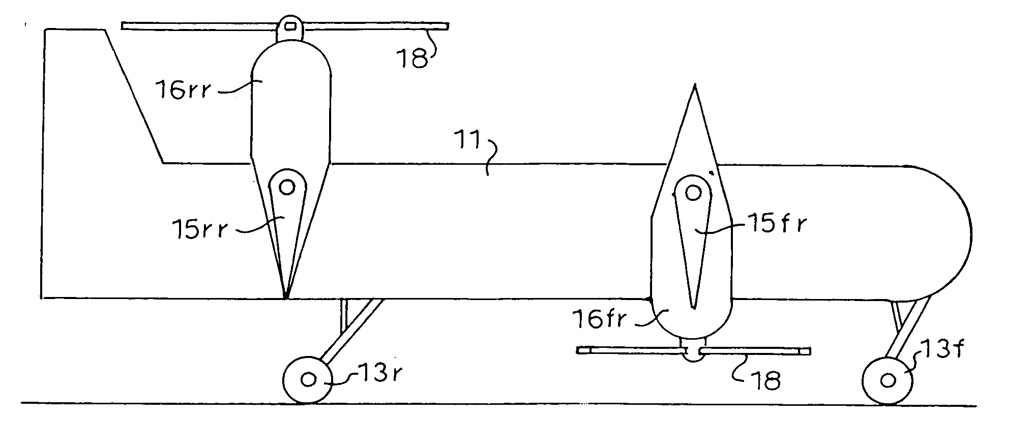
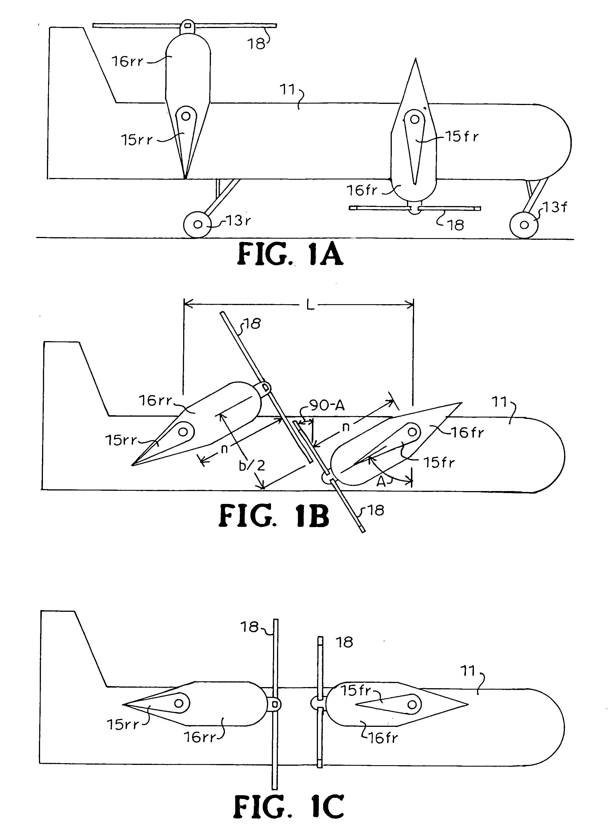
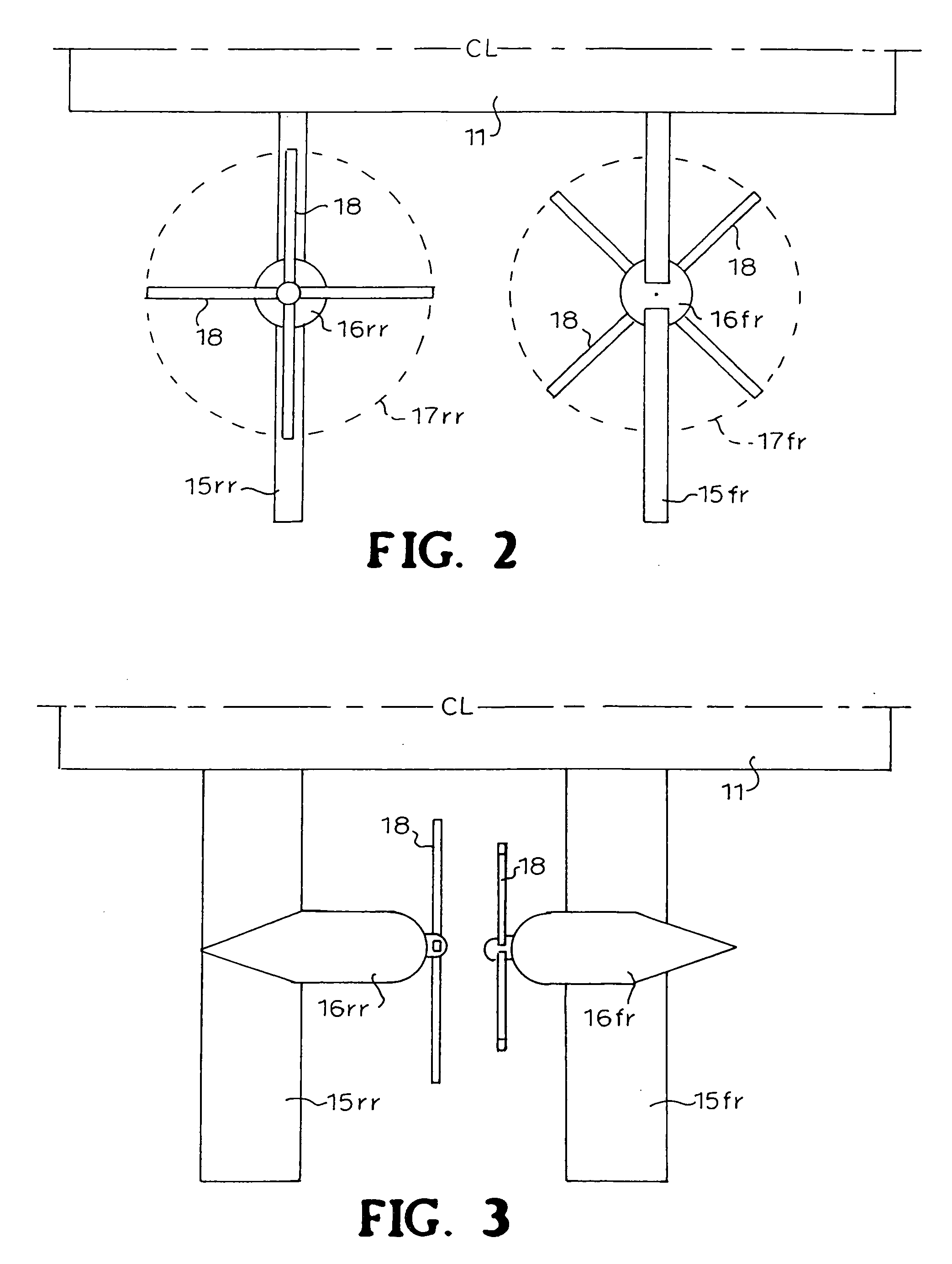
[0013] Referring now to FIGS. {1A, 1B, 1C} featuring elevation views of the aircraft right side, it is seen that in the VTOL configuration (FIG. {1A}) the rear wing-propulsor unit is pointed upward while the fore wing-propulsor unit is pointed downward. In each case the air is directed downward which is to say the rear propulsor is a “tractor” rotor while the fore propulsor is a “pusher” rotor. In the transition maneuver, both units rotate clockwise, directing air progressively rearward. The rotor planes or power discs pass through each other (FIG. {1B}) without collision because of their opposite directions of rotation and under the assumptions that (1) they are geared together as mesh-rotors and (2) the rotor diameter b is not large enough to allow blade contact of opposite hubs during pass-through. Finally, the power discs are aligned and relatively adjacent, as counter-rotating propellers, in level flight (FIG. {1C}). The before-and-after plan views of the configuration's right ...


PUM


Abstract

The invention consists of a specific, matched arrangement of aeronautical elements which (1) eliminates aerodynamic interference of, and (2) adds variable-cycle propulsion to, the level flight mode of a four-propulsor tilt-wing VTOL (vertical takeoff & landing) aircraft, without an additional element of variable geometry. This is achieved by configuring the components such that the rotor planes on either side pass through each other in the transition maneuver to form adjacent, close-coupled, counter-rotating pairs in level flight.

Description

BACKGROUND OF THE INVENTION [0001] The design herein described exploits a proven repertory of separate technologies as surveyed below. [0002] Both tilt-wing and tilt-rotor designs have been constructed and flown for many years. In each case, the propellers or rotors direct the air downward in the VTOL vertical flight mode and rearward in the level flight mode. Both concepts have their partisans, and both have advantages and disadvantages. In the present description, the tilt-wing has been preferred on the basis of its simpler, more predictable lifting surface / rotor wake aerodynamic interactions. Reference [1] provides an excellent 31-page summary of historical and contemporary tilt-wing aircraft of many companies. [0003] Straightforward engineering enables meshed-rotor configurations wherein rotor planes overlap, in the fashion of a traditional egg-beater. Both shafts are driven off a single master gear, preserving a set angular displacement. Since any transmission failure normally ...

Claims


Application Information

Patent Timeline
IPC IPC(8): B64C27/22B64C29/00B64C39/08
CPCB64C39/08B64C29/0033
Inventor HURLEY, FRANCIS X.
Owner HURLEY FRANCIS X
Why Eureka
Try Eureka