Light modulating microdevice

a micro-device and light-modulating technology, applied in the field of spatial light-modulators, can solve the problems of reducing size, difficult to obtain high-fill factor, and general limited tilt angl

Inactive Publication Date: 2005-10-20
HER MAJESTY THE QUEEN AS REPRESENTED BY THE MINIST OF NAT DEFENCE OF HER MAJESTYS CANADIAN GOVERNMENT +1
View PDF22 Cites 60 Cited by
  • Summary
  • Abstract
  • Description
  • Claims
  • Application Information

AI Technical Summary

Benefits of technology

[0053] Therefore, in accordance with the present invention, there is provided a mirror for light modulators, comprising a light-receiving member, at least one hinge adapted to be provided at an upper end thereof with said light-receiving member, said light-receiving member being flexible, said hinge being adapted to extend below said light-receiving member and being displaceable between deformed and extended positions thereby allowing for at least one of the displacement and the deformation of said light-receiving member.
[0055] Further in accordance with the present invention, there is provided a hinge assembly for supporting a flexible mirror in a light modulator, comprising at least one hinge including first and second arms hingedly connected together, an upper end of said hinge being adapted to be connected to the mirror, said first and second arms of said hinge being V-shaped and defining an apex, said hinge being adapted to extend substantially under the mirror with said apex extending inwardly, said hinge being displaceable between deformed and extended positions thereof, thereby allowing for the displacement and deformation of the mirror.
[0056] Still further in accordance with the present invention, there is provided a light modulator comprising a flexible mirror, a substrate provided with at least one electrode and at least one hinge connecting said substrate and said mirror, said hinge including first and second arms hingedly connected together, an upper end of said hinge being connected to said mirror, said first and second arms of said hinge being V-shaped and defining an apex, said hinge extending substantially under the mirror with said apex extending inwardly, said hinge being displaceable for allowing for the displacement and deformation of said mirror.

Problems solved by technology

Since large vertical distances are difficult to obtain using thin film processing technologies, tilt angles are generally limited to small values.
Because of processing considerations, high fill factors become more difficult to obtain as mirror size is reduced.
It is noted that this construction makes mass production of the device rather difficult.
One reason was undoubtedly due to the poor contrast of projection systems employing the device, since its operation requires a Schlieran configuration (or equivalent).
While the torsion hinge design is suitable for small mirrors, it does not work well for large mirrors; larger structures will tend to sag in the middle if support is provided only at their edges.
In addition, because the hinges must be thin, and long, they generally exhibit a low thermal conductance.
This reduces the mirrors capability to adequately dissipate heat, which can result in irreversible damage should it be employed for modulation of high energy beams.
As was mentioned earlier, torsion hinges need to be fairly long for sufficient flexibility thereby limiting the packing density of mirrors supported by such hinges.
For the small mirrors, the fill factor is inadequate using a one-level architecture.
One key drawback of this architecture is the complex fabrication process required and this manufacturing process is set forth in the Patent.
Despite this drawback, the small mirror size and high fill factors required for high-resolution projection displays has forced TI to employ this method of fabrication in their commercial DMD arrays.

Method used


Image

  • Light modulating microdevice
  • Light modulating microdevice
  • Light modulating microdevice

Examples


Embodiment Construction

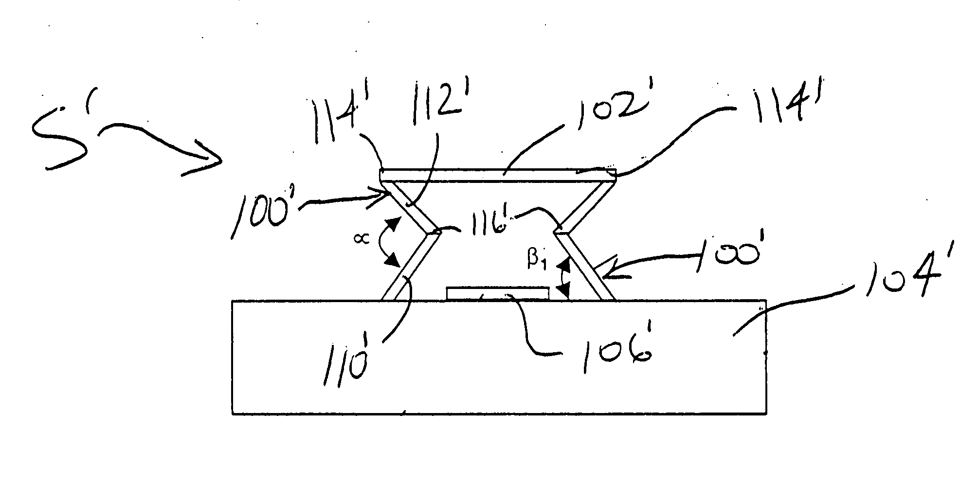
[0076] In accordance with the present invention, FIG. 8 illustrates a micro-SLM S in accordance with a first embodiment of the present invention. The micro-SLM S comprises a pair of hinges 100, a flexible mirror 102, a substrate 104 and an electrode 106 deposited on the substrate 104. The hinges 100 are integrated with the mirror 102. The mirror 102 is connected to the substrate 104 via the hinges 100 such that the mirror 102 is spaced from the substrate 104, as seen in FIG. 8.

[0077] In the drawings, there are shown two such hinges 100 for supporting the mirror 102. However, it is readily understood that a plurality of hinges 100 can be used to support a single mirror, particularly if the mirror is large. It is also possible to have a single hinge. The hinges 100 and the mirror 102 are electrically conductive so that the mirror 102 can be electrostatically actuated.

[0078] The mirror 102 may, when unbiased (i.e. when the hinges 100 are in their undeformed or at-rest position thereo...


PUM


Abstract

A light modulator comprises a mirror, a substrate provided with at least one electrode, and at least one hinge extending between the substrate and the mirror. The mirror is flexible with the hinge being displaceable for allowing for the displacement and / or the deformation of the mirror. Typically, there are two symmetrically disposed hinges, each including upper and lower arms that define an angle therebetween. The upper arm is connected to the mirror, and the lower arm is mounted to the substrate. The upper and lower arms are adapted to pivot relative to one another thereby allowing the angle to vary and thus allowing the mirror to at least one of displace and deform. When unbiased, the mirror may be plane, convex or concave. When biased, the plane mirror adopts a curved attitude, whereas the curved mirror changes its curvature. The upper and lower arms of each hinge are V-shaped and define an apex. The apexes extend inwardly in a facing relationship.

Description

BACKGROUND OF THE INVENTION [0001] 1. Field of the Invention [0002] The present invention relates to spatial light modulators (SLM) for amplitude and phase modulation of incident light and, more particularly, to a mirror and to a hinge mechanism for miniaturized spatial light modulators. [0003] 2. Description of the Prior Art [0004] Microdevices for light modulation go back 20 years or more. In the majority of cases, these devices are comprised of an electrostatically actuated mirror, supported by torsion bars along the axis of rotation of the mirror. A classic example can be found in U.S. Pat. No. 4,317,611 issued on Mar. 2, 1982 to Petersen, in which an “Optical Ray Deflection Apparatus” is described. [0005] The following United States Patents and Patent Application Publications are also known. U.S. Pat. No.Issue DateInventor(s)3,886,310May 27, 1975Guldberg et al.4,615,595Oct. 7, 1986Hornbeck4,662,746May 5, 1987Hornbeck5,061,049Oct. 29, 1991Hornbeck5,083,857Jan. 28, 1992Hornbeck5...

Claims


Application Information

Patent Timeline
Patent Type & Authority Applications(United States)
IPC IPC(8): G02B5/08G02B26/00G02B26/08
CPCG02B26/0841
Inventor ALAIN, CHRISTINEPICARD, FRANCISJEROMINEK, HUBERT
Owner HER MAJESTY THE QUEEN AS REPRESENTED BY THE MINIST OF NAT DEFENCE OF HER MAJESTYS CANADIAN GOVERNMENT
Why Eureka
Try Eureka