Method for recognizing location move of VoIP phones

a technology of voip phones and location moves, applied in the field of telephone systems and data systems, can solve the problems of out-of-date dn to ali mappings, increased phone mobility, and lack of knowledge on the part of the administrator that the phone has been moved

Inactive Publication Date: 2005-10-20
MITEL
View PDF8 Cites 59 Cited by
  • Summary
  • Abstract
  • Description
  • Claims
  • Application Information

AI Technical Summary

Benefits of technology

[0015] According to the present invention, the IP phone (or other IP device) detects its own current location and then informs the PBX controller (or location database, if the IP device is not an IP phone) during the phone's registration phase or as soon as a change is detected. The capability is integrated in every IP phone. The PBX then takes appropriate action, such as updating the ALI mapping for the phone. One significant difference between the present invention and the prior art is that the location information is captured by the IP phone (which is best suited to know where it is). As a result, the method of the present invention is more reliable and provides timely location information than the prior art. The method of the invention is also superior in that it uses no other external software systems to collect the location information.

Problems solved by technology

However, this increase in phone mobility gives rise to a lack of knowledge on the part of the administrator that the phone has been moved.
This can lead to problems, particularly in maintaining accurate location information for E911 services.
However, as indicated above, IP phones can be physically moved from one network node to another, with no system administrator intervention (although this may not be encouraged by the administrator).
When an IP phone is moved, its location may be different from the location referred to by the ALI that was originally programmed for it, resulting in out-of-date DN to ALI mappings.
One disadvantage to this solution is that a large number of very granular DHCP servers are required, which is not economically or managerially practical.
The expense of including such a GPS device within the IP phone or IP device would be prohibitive to gaining wide acceptance in the industry.
The foregoing prior art solutions require external software systems to collect the location information, thereby contributing to complexity and expense.
Moreover, the prior art solutions require additional hardware or expensive software to be added to the network, thereby adding to the cost of the overall system.
The information can be retrieved on a scheduled basis that does not allow for instantaneous recognition of a phone move.
In the GPS case, expensive embedded transmitters and external systems would be required to achieve the same goals.

Method used


Image

  • Method for recognizing location move of VoIP phones
  • Method for recognizing location move of VoIP phones

Examples


Embodiment Construction

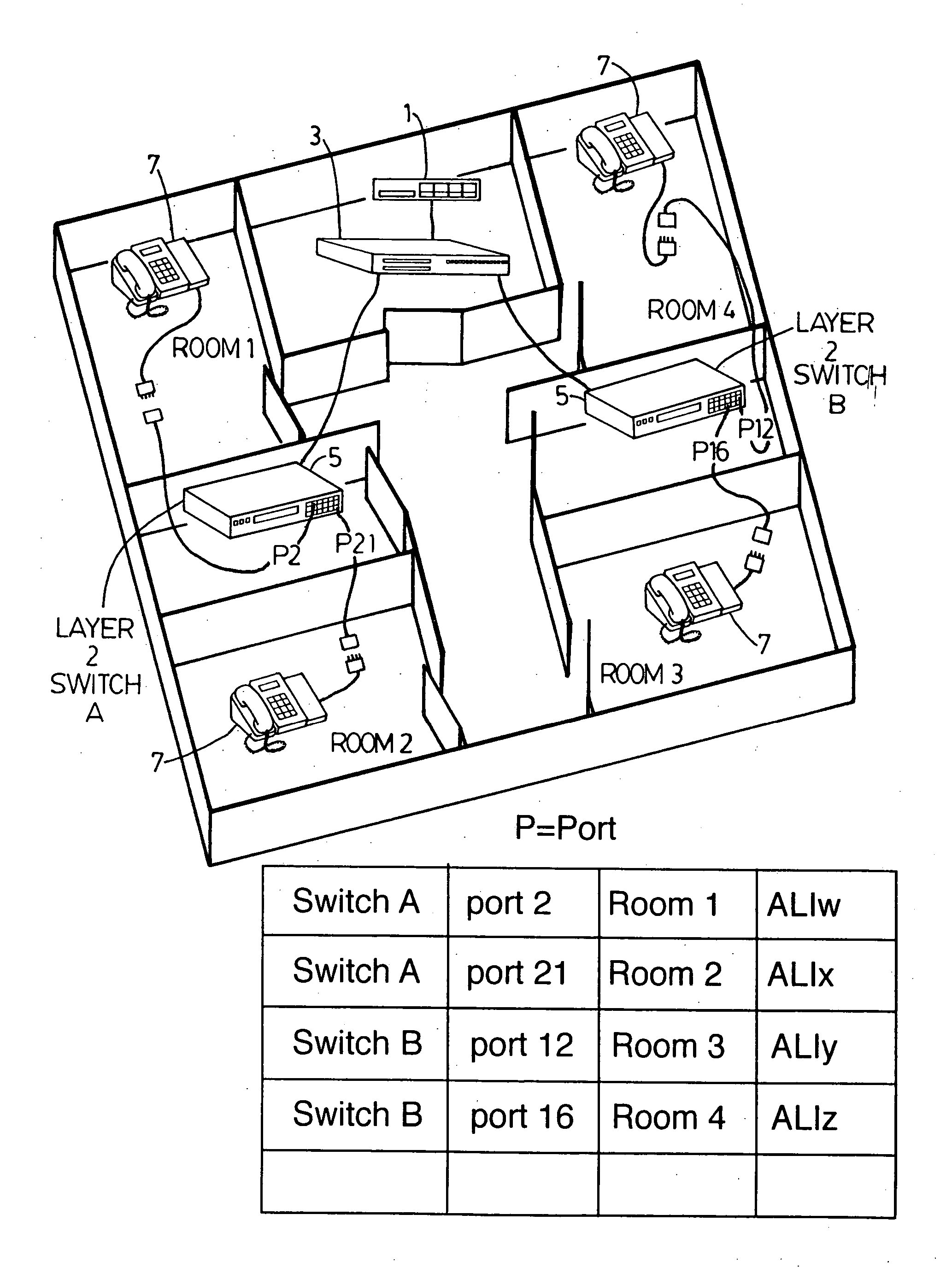
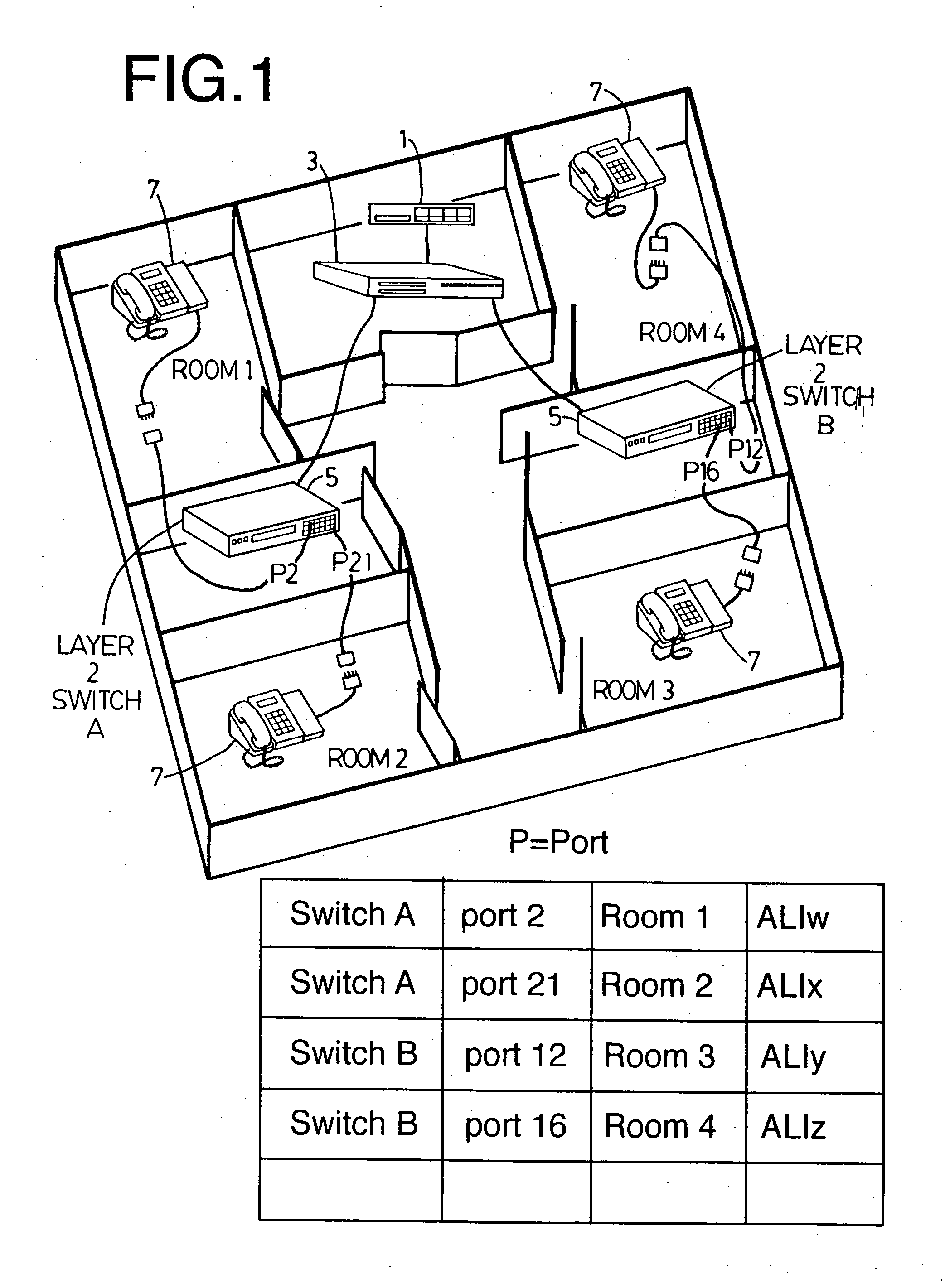
[0019]FIG. 1 depicts a communications network environment (e.g. a LAN) within a building (or spread over a number of buildings via a WAN) having a plurality of network devices such as computers, printers, and IP phones (the computers, printers, etc. not being shown). An iPBX 1, such as the MN3000 Integrated Communications Platform (ICP) manufactured by Mitel Networks Inc. provides traditional PBX functionality along with advanced features, over a data network (e.g. LAN). The iPBX 1 is connected to a router 3 in a well-known manner. A plurality of IEEE Layer 2 switches 5, each having multiple ports, are disposed in various rooms and are connected to the router 3. A plurality of IP devices, such as IP phones 7, are connected to the L2 switches 5.

[0020] In order for the IP phones to recognize where they are connected in the network hierarchy, the LAN is programmed to issue either the IEEE 802.1 Spanning Tree Protocol, the standard global 802.1ab Link Layer Discovery Protocol, or any p...


PUM


Abstract

A method is provided for tracking the physical location of IP phones and IP devices in a network. According to the invention, the IP phone or IP device detects its own current location and then informs the PBX controller or the location database to which it is connected. The capability is integrated in every IP phone and IP device. The PBX or location database then takes appropriate action, such as updating the ALI mapping for the phone or location information for the IP device.

Description

BACKGROUND OF THE INVENTION [0001] 1. Field of the Invention [0002] The present invention relates generally to telephone systems and data systems, and more particularly to a method of tracking the physical location of VoIP phones and IP devices in a closed environment. [0003] 2. Description of the Related Art [0004] One of the benefits of VoIP technology is that an IP phone can be moved from one physical location to another without administrator intervention to, effect the change. Connectivity between the IP phone and that PBX is via IP messaging over a data network. However, this increase in phone mobility gives rise to a lack of knowledge on the part of the administrator that the phone has been moved. This can lead to problems, particularly in maintaining accurate location information for E911 services. [0005] Support of Emergency Services requires Automatic Location Identification (ALI) number to be sent to a Public Safety Answering Point (PSAP) when an emergency service number (...

Claims


Application Information

Patent Timeline
Patent Type & Authority Applications(United States)
IPC IPC(8): H04L12/24H04L29/06H04L29/08H04L29/12H04M3/42H04M7/00
CPCH04L29/06H04L29/06027H04L29/12839H04L41/12H04L61/6022H04L69/329H04M3/42314H04M3/42357H04M2242/04Y02B60/43H04L67/18H04L65/1073Y02D30/00H04L2101/622H04L67/52H04L9/40H04L65/1101
Inventor ANZAROUTH, RALPHNASON, CHRISFODOR, JOHNMACMASTER, JOHNPATRY, JEAN YVESFU, SHUNQIU SUEHERR, DAVIDSZPILFOGEL, CHRISTIANKUS, ED
Owner MITEL
Why Eureka
Try Eureka