Out-of-band data communication between network transceivers

a network transceiver and data communication technology, applied in electromagnetic transceivers, transmission monitoring, electromagnetic transmission, etc., can solve the problems of time delays, data processing, data processing cost, and data processing cost significant and unwanted costs of the data processing

Active Publication Date: 2005-10-20
II VI DELAWARE INC
View PDF99 Cites 59 Cited by
  • Summary
  • Abstract
  • Description
  • Claims
  • Application Information

AI Technical Summary

Benefits of technology

[0025] In this manner, embodiments of the invention enable out-of-band data to be transmitted simultaneously with high-speed data on the high-speed data physical link. This may allow for monitoring transceiver health, remotely configuring transceivers, authenticating transceivers etc.
[0026] These and other advantages and features of the present invention will become more fully apparent from the following description and appended claims, or may be learned by the practice of the invention as set forth hereinafter.

Problems solved by technology

In other words, transceivers do not generally communicate data to one another for the benefit of the transceivers.
This may cause various difficulties when the host and transceiver are located in a remote location such as on the ocean floor or in remote desert locations.
To disassemble and reassemble a high-speed data signal represents a significant and unwanted cost in terms of data processing.
Additionally, there are time delays as the data is disassembled and reassembled prior to retransmission of the data from link to link.
This implementation cannot be used in single channel systems.
Further, the use of a channel for diagnostic data reduces the amount of other high-speed data that can be transmitted.
Also, the cost of disassembling and reassembling the high-speed data signal remains as the channel with the digital diagnostic data must be extracted from the high-speed data signal to obtain the digital diagnostic data and re-added to the high-speed data signal when the high-speed data signal is passed to other links in a network.
Another challenge that arises with transceivers presently in the art relates to negotiating data rates along a channel.
Presently existing negotiation protocols are complex and may require inordinate amounts of network and computing resources to properly negotiate a data rate.

Method used


Image

  • Out-of-band data communication between network transceivers
  • Out-of-band data communication between network transceivers
  • Out-of-band data communication between network transceivers

Examples


Embodiment Construction

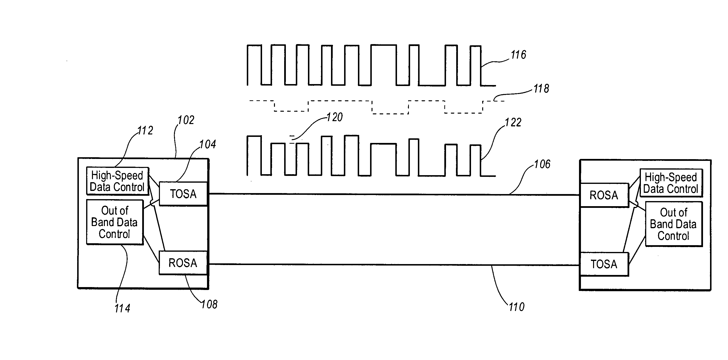
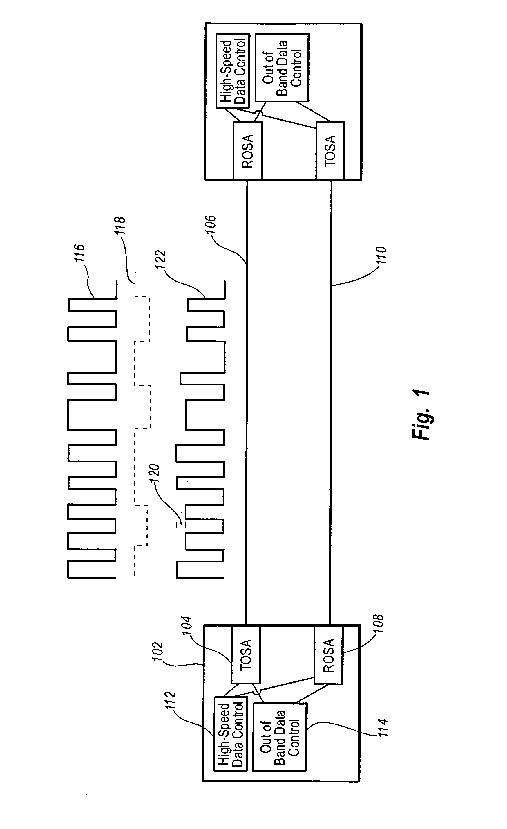
[0046] Embodiments of the present invention include systems and methods for modulating high-speed data and out-of-band data as a double modulated signal. The double modulated signal is transmitted on a physical link between components in a network of connected hosts. Thus, high-speed data that is ordinarily transmitted on a physical link can be transmitted with out-of-band data on the same physical link. This allows for the transmission of information such as diagnostic information, authentication information, rate negotiation information, configuration information etc.

[0047] The term “high-speed data,” as used herein, does not refer to any particular defined bandwidth or frequency of data. Rather, high-speed data refers to data typically transmitted on a network such as the data typically transmitted for the benefit of the various hosts on a network. High-speed data may also be referred herein as in-band data which is a reference to the communication band typically used by host sy...


PUM


Abstract

Out-of-band data communication of diagnostic or other data is performed using transceivers in a data or communication network. A light beam or other carrier is modulated with high-speed data and out-of-band data to create a double modulated data signal. A physical layer signal is created that includes modulations of the double modulated signal. The physical layer signal is transmitted onto a physical link. The diagnostic or other data can be transmitted in the out-of-band signal without substantially reducing or otherwise interfering with the transmission rate of the high-speed data.

Description

BACKGROUND OF THE INVENTION [0001] 1. The Field of the Invention [0002] The invention generally relates to the field of data transmission in communication networks. More specifically, the invention relates to simultaneous transmission of high-speed data and out-of-band data. [0003] 2. Description of the Related Art [0004] Modem day communication is, in large part, accomplished by transmitting and receiving large amounts of digital data. Digital data signals can be used to transmit information such as database information, financial information, personal and business information, and the like. In addition, digital data signals can be used to transmit voice, video, images etc. [0005] Commonly, digital communication is accomplished using a model known as the Open Systems Interconnection (OSI) model. The OSI model defines a framework for accomplishing digital communications with seven layers on clients communicating in a network. These seven layers are understood by those of skill in th...

Claims


Application Information

Patent Timeline
Patent Type & Authority Applications(United States)
IPC IPC(8): H04B10/00H04B10/04H04B10/152H04B10/43
CPCH04B10/40H04B10/152H04B10/25H04B10/00
Inventor ARONSON, LEWHOSKING, LUCYMATUSZKIEWICZ, MARCINMASON, BECK
Owner II VI DELAWARE INC
Why Eureka
Try Eureka