
Image forming apparatus and image forming system

a technology of image forming apparatus and pantograph pattern, which is applied in the direction of digital output to print units, electrographic processes, instruments, etc., can solve the problems of lack of convenience, difficulty in changing the pantograph pattern, and increase the printing cos

Inactive Publication Date: 2005-10-20
SHARP KK
View PDF17 Cites 13 Cited by
  • Summary
  • Abstract
  • Description
  • Claims
  • Application Information

AI Technical Summary

Benefits of technology

[0011] In the present invention, when forming an image by compositing received image data and image data stored in the storing means together, a determination is made as to whether or not image formation based on the resulting composite image data is possible, and then the image formation is executed or stopped according to the determination result. Therefore, when the determining means determines that it is impossible to form the resulting composite image due to deterioration of various parts and consumable supplies in the means for forming an image, it is possible to control the apparatus to stop the image formation. As a result, the quality of the image to be outputted can be maintained at a fixed level, and, for example, an image such as a pantograph pattern that requires fine gradation representation can be provided as printed material only when it is possible to faithfully reproduce the gradation representation.
[0046] According to the present invention, a determination as to whether or not to transmit image data is made based on the information indicating whether or not image formation is possible. Therefore, when the image forming apparatus determines that it is impossible to form the resulting composite image due to deterioration of various parts and consumable supplies in the means for forming an image, it is possible to control the apparatus to stop the transmission of image data. As a result, the quality of the image to be outputted can be maintained at a fixed level, and, for example, an image such as a pantograph pattern that requires fine gradation representation can be provided as printed material only when it is possible to faithfully reproduce the gradation representation.

Problems solved by technology

However, since it is necessary to prepare the paper on which a pantograph pattern is printed in advance, such a technique has the problem of an increase in the printing cost.
Moreover, since predetermined characters and patterns for restricting copying are used, it is difficult to change the pantograph pattern according to a document, and thus this technique also has the problem of lack of convenience.
By the way, in a printing apparatus that forms an image by electrophotographic processes, when consumable supplies such as a photosensitive drum and developer deteriorate and need to be replaced, or when the printing apparatus is in a period of adjustment, the printing apparatus may fail to faithfully reproduce the gradations of the pantograph pattern.
If it is impossible to faithfully reproduce the gradations of the pantograph pattern, an image intended to appear when a copy is made will not appear, and consequently there arises a problem that the effect of the pantograph pattern that restrains copying may not be sufficiently exhibited.

Method used


Image

  • Image forming apparatus and image forming system
  • Image forming apparatus and image forming system
  • Image forming apparatus and image forming system

Examples


embodiment 1

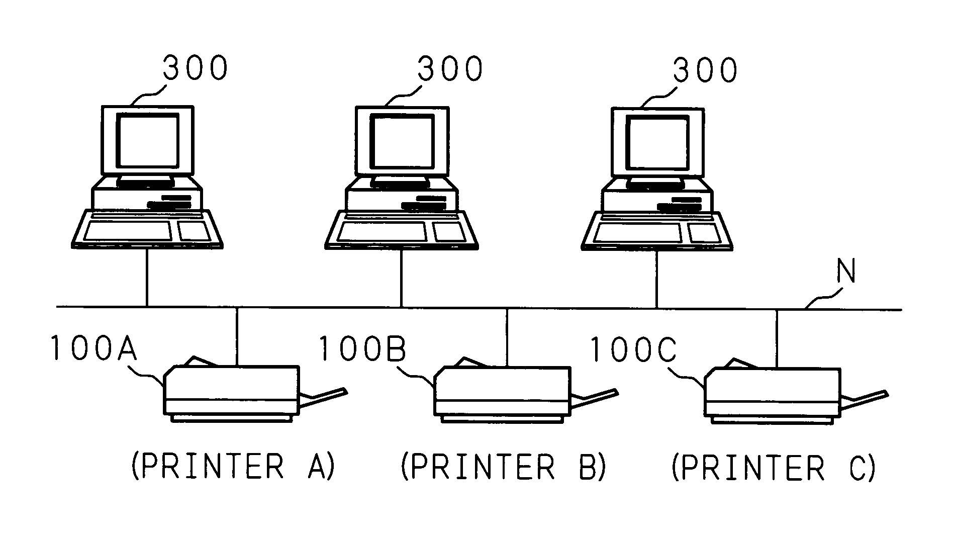
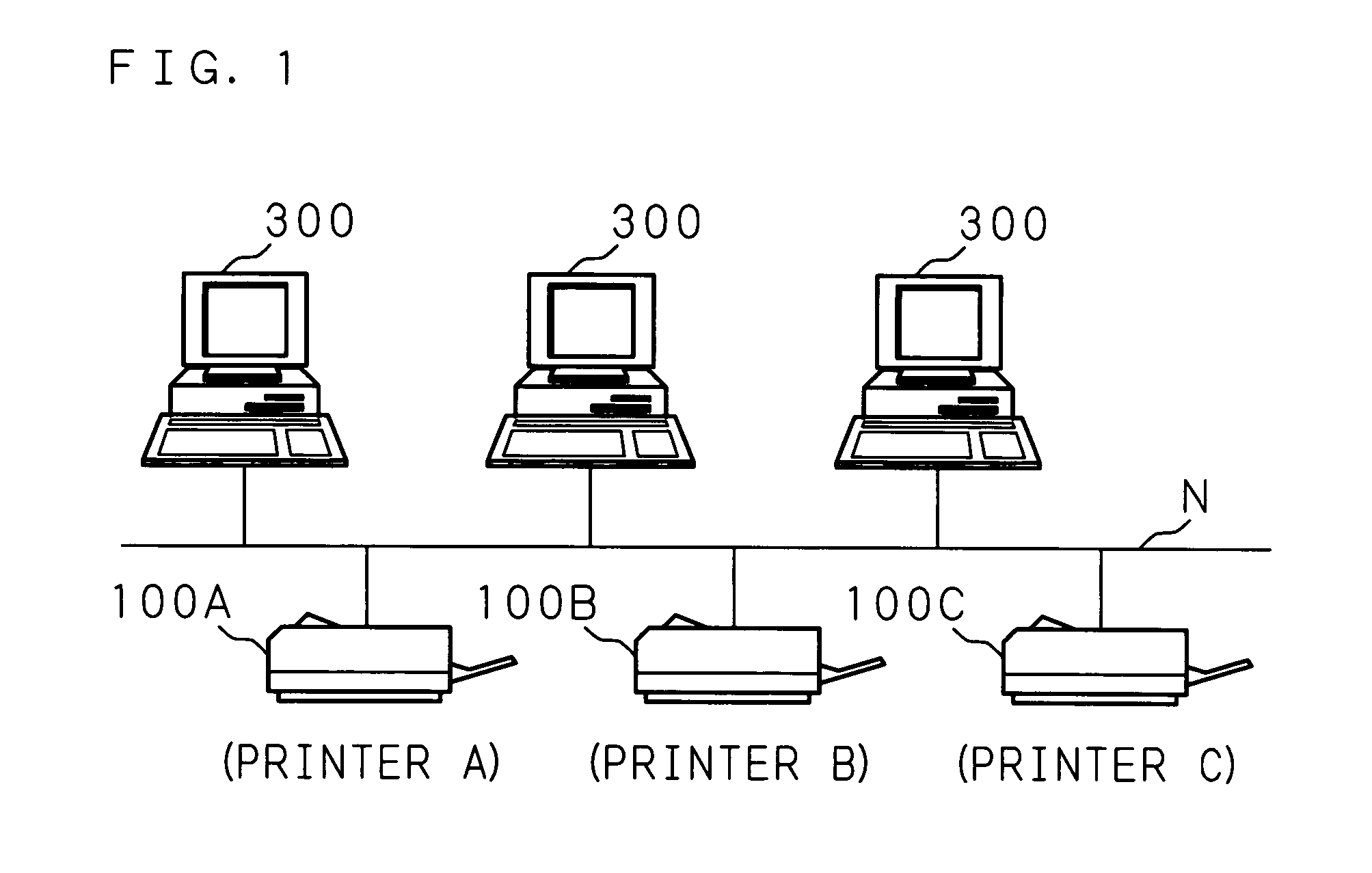
[0061]FIG. 1 is a schematic view showing the entire structure of an image forming system according to this embodiment. In FIG. 1, 100A, 100B and 100C represent printing apparatuses for forming an image on a sheet of paper, OHP film, etc., and information processing apparatuses 300, 300, 300 such as personal computers and workstations are connected to these printing apparatuses 100A, 100B and 100C through communication network N. In the information processing apparatus 300, application programs for creating documents, graphics, etc. and a driver program (printer driver) for using the printing apparatus 100A, 100B or 100C through the communication network N are installed in advance, and the information processing apparatus 300 can output prints of created documents, graphics, etc. by calling the printer driver from an arbitrary application program and transmitting print jobs created by the printer driver to a target printing apparatus 100A (or printing apparatus 100B or 100C).

[0062] ...

embodiment 2

[0080] In Embodiment 1, the printing apparatus 100 which received a print job confirms the condition of the image forming section 107 and determines whether or not it is possible to reproduce a pantograph pattern, and then gives information based on the determination result to the information processing apparatus 300 which sent this print job. However, if a network is constructed to send a print job through a print server, it may also be possible to manage the apparatus information about the respective printing apparatuses 100A, 100B and 100C by the print server, and determine the reproducibility of a pantograph pattern when the print server receives a print job.

[0081]FIG. 6 is a schematic view showing the entire structure of an image forming system according to this embodiment. A print server 200 is connected to information processing apparatuses 300, 300, 300 such as personal computers and workstations through communication network N, and a plurality of printing apparatuses 100A,...


PUM


Abstract

In an image forming apparatus having storing means for storing image data to be composited with received image data, means for compositing the image data with the received image data, means for forming an image based on the resulting composite image data, and determining means for determining whether or not image formation is possible, the image formation based on the image data is executed or stopped according to the determination result of the determining means.

Description

CROSS-REFERENCE TO RELATED APPLICATIONS [0001] This non-provisional application claims priority under 35 U.S.C. §119(a) on Patent Application No. 2004-41911 filed in Japan on Feb. 18, 2004, the entire contents of which are hereby incorporated by reference. BACKGROUND OF THE INVENTION [0002] 1. Field of the Invention [0003] The present invention relates to an image forming apparatus and an image forming system, capable of adding an image for restraining copying to printed material. [0004] 2. Description of Related Art [0005] As one of techniques for preventing copying of printed material, a technique using a pantograph pattern in the background of a document which is prohibited from being copied has been known. A pantograph pattern consists of dots (foreground dots) in a size that remain even when a copy is made using a copying machine, and dots (background dots) which are so small and disappear when a copy is made. The background dots are provided around the foreground dots so that ...

Claims


Application Information

Patent Timeline
Patent Type & Authority Applications(United States)
IPC IPC(8): B41J29/38B41J21/00B41J29/46B42D15/10G03G15/00G03G15/36G03G21/00G03G21/04G06F3/12G06T1/00H04N1/387
CPCG03G15/50G03G2215/00582G03G2215/00316G03G2215/00113
Inventor SYOUICHIRO, YOSHIURA
Owner SHARP KK
Learn More