Method and Apparatus For Inspecting Defect Of Pattern Formed On Semiconductor Device
a technology of semiconductor devices and defect detection, which is applied in the direction of semiconductor/solid-state device testing/measurement, image enhancement, instruments, etc., can solve the problems of pattern shape itself (systematic defect) which cannot be detected by comparison of image to image of such actual pattern, and the yield drop
- Summary
- Abstract
- Description
- Claims
- Application Information
AI Technical Summary
Benefits of technology
Problems solved by technology
Method used
Image
Examples
embodiment 1
[0058]As Embodiment 1, an embodiment will be described wherein variation of exposure condition is made a supposed defect occurrence factor and detection and classification according to the respective occurrence factor of the defect are performed.
[Total Parts Constitution]
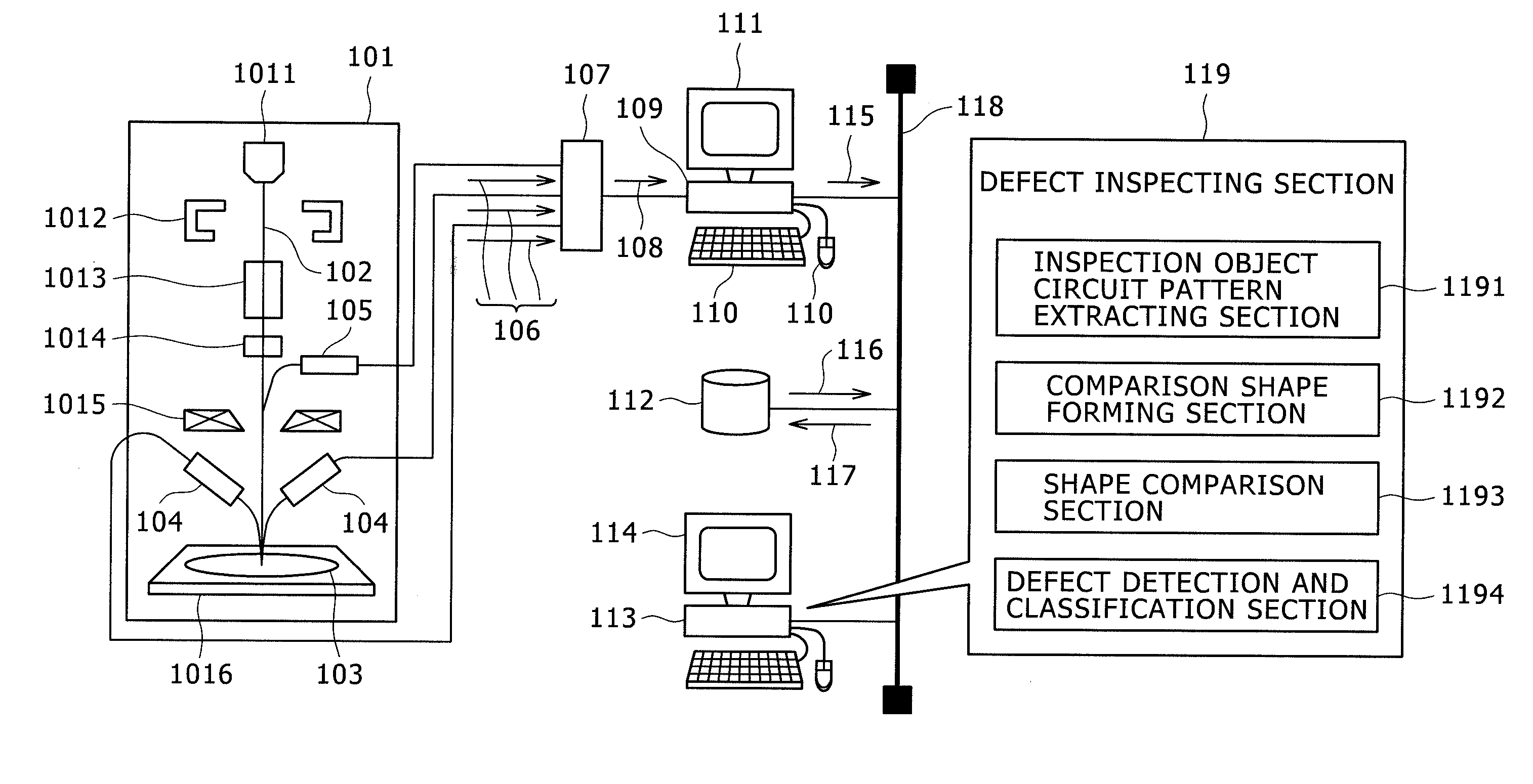
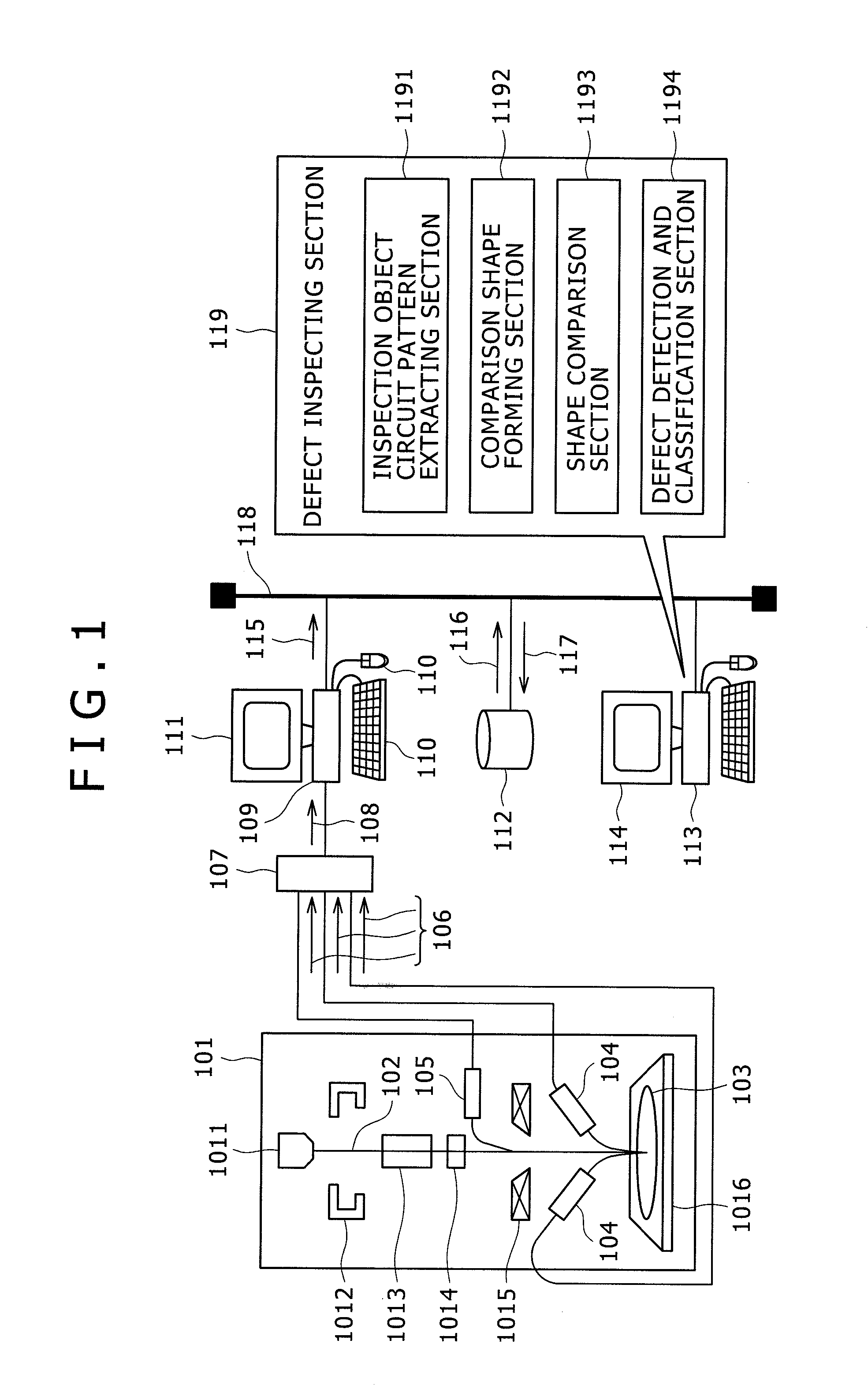
[0059]FIG. 1 is a schematic constitution drawing of the defect inspection apparatus with a SEM for detection and classification of the defect on a semiconductor wafer in accordance with an embodiment of the present invention.
[0060]101 is a SEM comprising in its inside; an electron source 1011, an extraction electrode 1012 for extracting an electron emitted from the electron source 1011 by desired acceleration energy in a beam shape, scanning electrodes 1013, 1014 for scanning an electron beam 102 extracted by the extraction electrode 1012 by the desired acceleration energy in a beam shape two-dimensionally in X or Y direction, a lens electrode 1015 for adjusting the focusing position of the electron beam 102 in orde...
embodiment 2
[0114]As Embodiment 2, an embodiment will be described wherein variation of exposure condition and an error in an overlay position occurring between layers are made supposed defect occurrence factors, and detection and classification are performed with respect to an abnormal exposure condition defect, an overlay position error defect, and a defect caused by a plurality of non-supposed defect occurrence factors. As the present embodiment is similar to Embodiment 1 with respect to apparatus constitution and process steps, only the points different in processing contents will be described.
[0115]FIG. 20 is an explanatory drawing of a comparison shape forming section in accordance with the present embodiment. Here, explanation will be made using double layer design data. Based on design data 2001, a comparison shape set 2004 is formed by the comparison shape forming section 1192. At this time, shape deformation is performed in accordance with an exposure condition variation shape deforma...
embodiment 3
[0120]As Embodiment 3, an embodiment will be described referring to FIG. 17 wherein defect detection and classification is performed when the number of supposed defect occurrence factors is made optional.
[0121]First, in a comparison shape forming section 1702, a comparison shape set 1703 is formed based on design data 1701. The comparison shape set 1703 is a group of a plurality of shapes added with deformation according to predetermined shape deformation rules 1711. The shape deformation rules 1711 are to stipulate a deformation method 17111 of the design data (information on deformation variation such as a deformation range 17112, and deformation quantity step 17113, for example) according to respective supposed defect occurrence factor such as variation of exposure condition, an error of an overlay position occurring between layers, and an overlay error in a multi-layer pattern, and can stipulate any number of variations. A deformation quantity set 1712 is an optional combination...
PUM
 Abstract
Description
Claims
Application Information
 - R&D
- Intellectual Property
- Life Sciences
- Materials
- Tech Scout
- Unparalleled Data Quality
- Higher Quality Content
- 60% Fewer Hallucinations
Browse by: Latest US Patents, China's latest patents, Technical Efficacy Thesaurus, Application Domain, Technology Topic, Popular Technical Reports.
© 2025 PatSnap. All rights reserved.Legal|Privacy policy|Modern Slavery Act Transparency Statement|Sitemap|About US| Contact US: help@patsnap.com


