Image forming apparatus and masking coefficient calculation method

a masking coefficient and image forming technology, applied in the field of image forming apparatus, can solve the problems of inability to calibrate, disabling faithful color, and inapplicability of chromatic color faithfulness technology

Inactive Publication Date: 2006-11-07
RICOH KK
View PDF16 Cites 19 Cited by
  • Summary
  • Abstract
  • Description
  • Claims
  • Application Information

AI Technical Summary

Benefits of technology

[0018]An object of the present invention is to provide an image forming apparatus which can calibrate variation of spectral characteristics of the scanner CCD, and obtain a CMYK output image signal which can reproduce a color faithfully without variation for documents of chromatic color.

Problems solved by technology

Also the difference can not be calibrated even by a shading calibration using an achromatic-colored reflection plate.
The difference becomes a cause of disabling faithful color reproduction in a color calibration process for obtaining record values of cyan, magenta, yellow and black optimal for reproducing the color from RGB values of a document read by the scanner.
However, there is a problem in that this technology is not applicable for reproducing chromatic color faithfully.
However, there is a problem in that it is not enough for performing faithful color reproduction for chromatic color.

Method used


Image

  • Image forming apparatus and masking coefficient calculation method
  • Image forming apparatus and masking coefficient calculation method
  • Image forming apparatus and masking coefficient calculation method

Examples


first embodiment

[0060]First, the first embodiment of the present invention will be described. The first embodiment is a case when a color calibration technique of the present invention is applied to an electronic photocopying machine (hereinafter, simply called as a copying machine) which is an image forming apparatus.

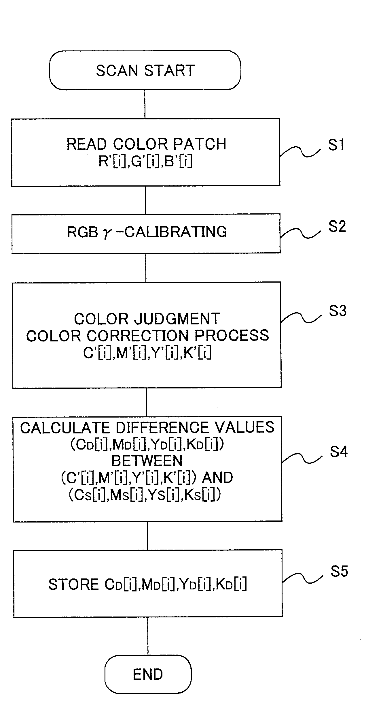
[0061]Although this invention mainly relates to correction or calculation of a masking coefficient for color calibration process performed in an after-mentioned color calibration circuit, a configuration and the operation of the copying machine will be described first with reference to FIGS. 2–4, and the color calibration process will be described in detail after that.

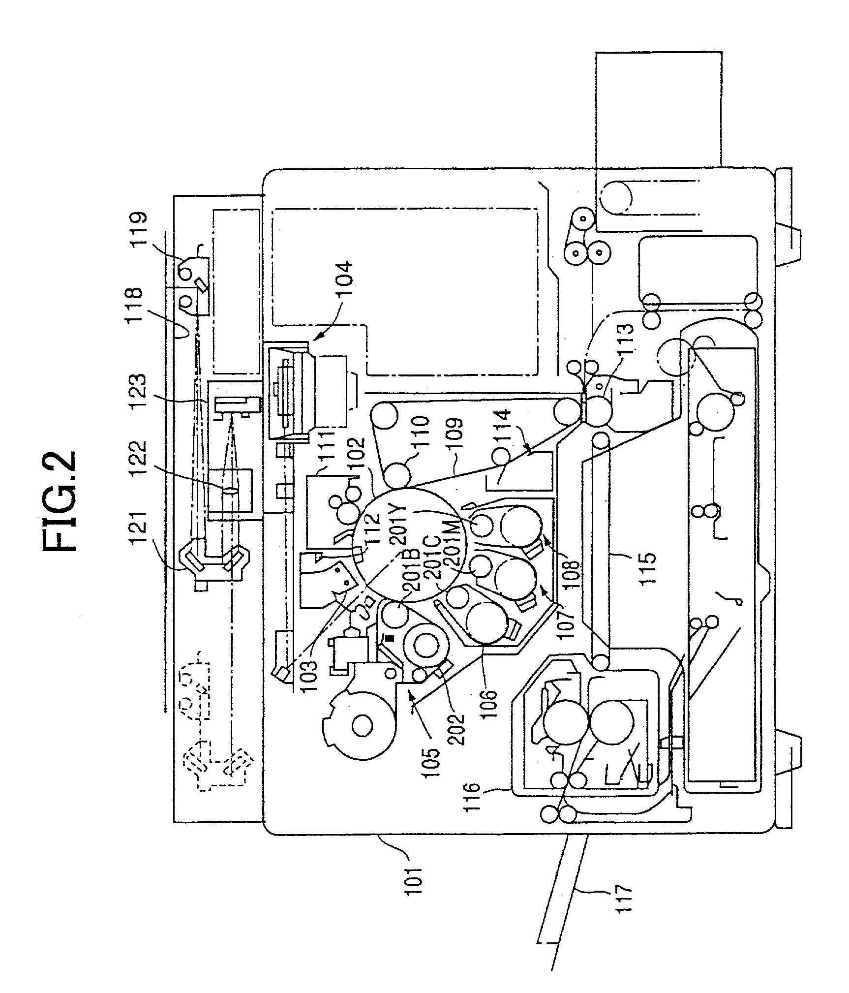
[0062]FIG. 2 is a schematic view showing mechanical configuration of the main body of a copying machine 101. Outline of the mechanism of the main body of the copying machine 101 of the present invention will be described with reference to FIG. 2.

[0063]In FIG. 2, an organic photosensitive (OPC) drum 102 having a diameter ...

second embodiment

[0127]In the first embodiment, the difference value is added to every printer vectors when calculating the corrected masking coefficient as shown in equation (11). As indicated by the equations 8 and 9, color calibration can be performed effectively by this method.

[0128]However, since the printer vectors of the white and black points are used for calculation of masking coefficients for every divided color space, when different correction values are used for each space, there is a case that discontiguous spaces are generated around the boundary planes near the white and black points.

[0129]In addition, for a printer vector of another point of the boundary point, by using difference values corresponding to the point, discontinuity on each boundary plane can be prevented.

[0130]In the second embodiment, in consideration of these points, in the above example using R patch, the correction values (CD[R],MD[R],YD[R],KD[R]) and (CD[M], MD[M],YD[M],KD[M]) corresponding to printer vectors of R ...

third embodiment

[0132]In the first and second embodiments, the masking coefficient is calculated by using the difference values indicated by the equation (4). In the third embodiment, a method for calculating the masking coefficient without using the difference values.

[0133]In a case where the color space is divided by points red (R), yellow (Y), green (G), cyan (C), blue (B), magenta (M)in the same way as the above mentioned embodiments, the masking coefficient (before correction) of the hue between R and Y can be represented by an equation (13).

[0134](acracgacbacamramgambamayraygaybayakrakgakbak)=(C⁡[R]C⁡[Y]C⁡[W]C⁡[K]M⁡[R]M⁡[Y]M⁡[W]M⁡[K]Y⁡[R]Y⁡[Y]Y⁡[W]Y⁡[K]K⁡[R]K⁡[Y]K⁡[W]K⁡[K])×(R⁡[R]R⁡[Y]R⁡[W]R⁡[K]G⁡[R]G⁡[Y]G⁡[W]G⁡[K]B⁡[R]B⁡[Y]B⁡[W]B⁡[K]1111)-1(13)

[0135]For example, assuming that values obtained by reading the R patch by a scanner CCD having variation of spectral characteristics is (R′[R],G′[R],B′[R]), values calculated by the masking coefficient of the equation (13) can be represented by a foll...


PUM

PropertyMeasurementUnit
diameteraaaaaaaaaa
coloraaaaaaaaaa
colorsaaaaaaaaaa

Abstract

An image forming apparatus for calculating a masking coefficient is provides, in which the masking coefficient is calculated by using RGB input image signals obtained by reading a document of which spectral characteristics are known by an image reading part and CMYK output image signals optimal for reproducing a color of the document. The masking coefficient can be also calculated by using difference values between CMYK output image signals obtained from actually read RGB signals and optimal CMYK output image signals.

Description

BACKGROUND OF THE INVENTION[0001]1. Field of the Invention[0002]The present invention relates to an image forming apparatus such as a copying machine, a printer and a FAX and the like. More particularly, the present invention relates to an image forming apparatus having a color conversion function for handling a color image.[0003]2. Description of the Related Art[0004]Conventionally, for performing color correction in a digital image forming apparatus, there is a technology in which a pattern image formed on an image carrier is transferred to a transfer material and fixed, and the transferred image is read by a scanner, and, then, a tone correction table is selected / generated on the basis of the read image data, so that tone correction or density correction of a printer part is performed.[0005]Japanese laid-open patent application No. 10-191061 discloses a technology in which the tone correction table is corrected in consideration of variation of spectral characteristics of the scan...

Claims


Application Information

Patent Timeline
Patent Type & Authority Patents(United States)
IPC IPC(8): G06K15/00B41J2/525G03F3/08G06T1/00H04N1/46H04N1/60
CPCH04N1/6033
Inventor SUGIYAMA, NAOKI
Owner RICOH KK
Why Eureka
Try Eureka