Image forming apparatus with reduced image defects

a technology of forming apparatus and reducing image defects, which is applied in the direction of electrographic process apparatus, instruments, optics, etc., can solve the problems of clogging of the nip between the developing roller and the regulating blade, uneven feed direction, and irregular feed on the developing roller

Inactive Publication Date: 2004-01-27
SEIKO EPSON CORP
View PDF20 Cites 18 Cited by
  • Summary
  • Abstract
  • Description
  • Claims
  • Application Information

AI Technical Summary

Benefits of technology

With the above-described structure, the present invention reduces the influence of the irregularity of feeding by the driving unit and minimizes the packing of the developer in the development nip, thereby increasing the degree of freedom with which the developer is movable, and faithfully reproducing the latent image to obtain a favorable image free from noise. In addition, the present invention minimizes fogging and scattering, reduces the occurrence of clogging with aggregates of developer and eliminates longitudinal strip-shaped unevenness and longitudinal stripes. Thus, it becomes possible to attain high image quality and to increase the lifetime of the system.

Problems solved by technology

Hence, the drive of the developing roller becomes unavoidably intermittent owing to the backlash in the mesh of the gears, causing feed irregularities to occur on the developing roller.
As a result, density unevenness (banding) occurs in the feed direction.
Further, when the thickness of the toner layer on the surface of the developing roller is regulated with the regulating blade, toner is likely to clog in the nip between the developing roller and the regulating blade.
This causes the image quality to be degraded.
In the contact development, toner may adhere to a non-image area, causing fogging.
Further, blur may occur in a halftone image owing to disconnection, thickening or scattering of thin lines of the image.
When printing is performed continuously, toner may adhere to the developing roller to give rise to a problem known as filming.
This causes the toner transferability and chargeability to change, resulting in image quality degradation.
As a result, small toner particles are repeatedly stirred and pressed, causing filming on the developing roller and the regulating blade (i.e. the problem in terms of durability).
However, this development method involves the problem that it is costly because a magnet is installed on the developing sleeve, and the method cannot cope with the demand for color image formation.
There are also problems inherent to this method.
Consequently, there may be undesired tailing produced by toner left uncollected by magnetic force (i.e. a phenomenon in which a trail of toner is undesirably left behind the image).
With this method, the amount of toner conveyed is large, but on the other hand, charging of toner is likely to become insufficient, causing fogging.
Problems to be solved for the non-magnetic one-component development, exclusive of the magnetic brush development, include gradation degradation due to edge enhancement and an increase in density at the trailing end of the image.
However, satisfactory improvements cannot be made by this method (i.e. the problem in terms of image quality, edge enhancement and fogging).
There is an image forming apparatus in which an image is formed by developing an electrostatic latent image formed on a latent image carrier (photosensitive member) by using a contact developing device arranged to apply an AC-superimposed bias voltage to a developer carrier (developing roller) This type of image forming apparatus involves the problem that the resulting image is unfaithful to the latent image and inferior in gradation reproduction and halftone reproduction and hence suffers from poor image quality.
However, the amplitude (V.sub.pp) of the AC-superimposed bias voltage cannot sufficiently be increased because of such restrictions as the injection of an electric charge into the latent image carrier and background fogging.
Accordingly, the conventional image forming apparatus of this type is not at a practical level.
However, this method involves the problem that noise may be generated depending on the screen structure or other factors.
For example, if a halftone dot screen is used in a case where a line-shaped conveying surface is formed on the developer carrier, banding (lateral unevenness) occurs unfavorably.
Further, if the frequency of the screen in the feed direction synchronizes to the frequency of a line-shaped conveying surface generated by application of an AC-superimposed bias voltage, density unevenness occurs on the latent image carrier.
If the frequency of the screen in the feed direction synchronizes to the frequency of the nip variations due to the superimposition of the alternating current, density unevenness occurs on the latent image carrier.

Method used


Image

  • Image forming apparatus with reduced image defects
  • Image forming apparatus with reduced image defects
  • Image forming apparatus with reduced image defects

Examples


Embodiment Construction

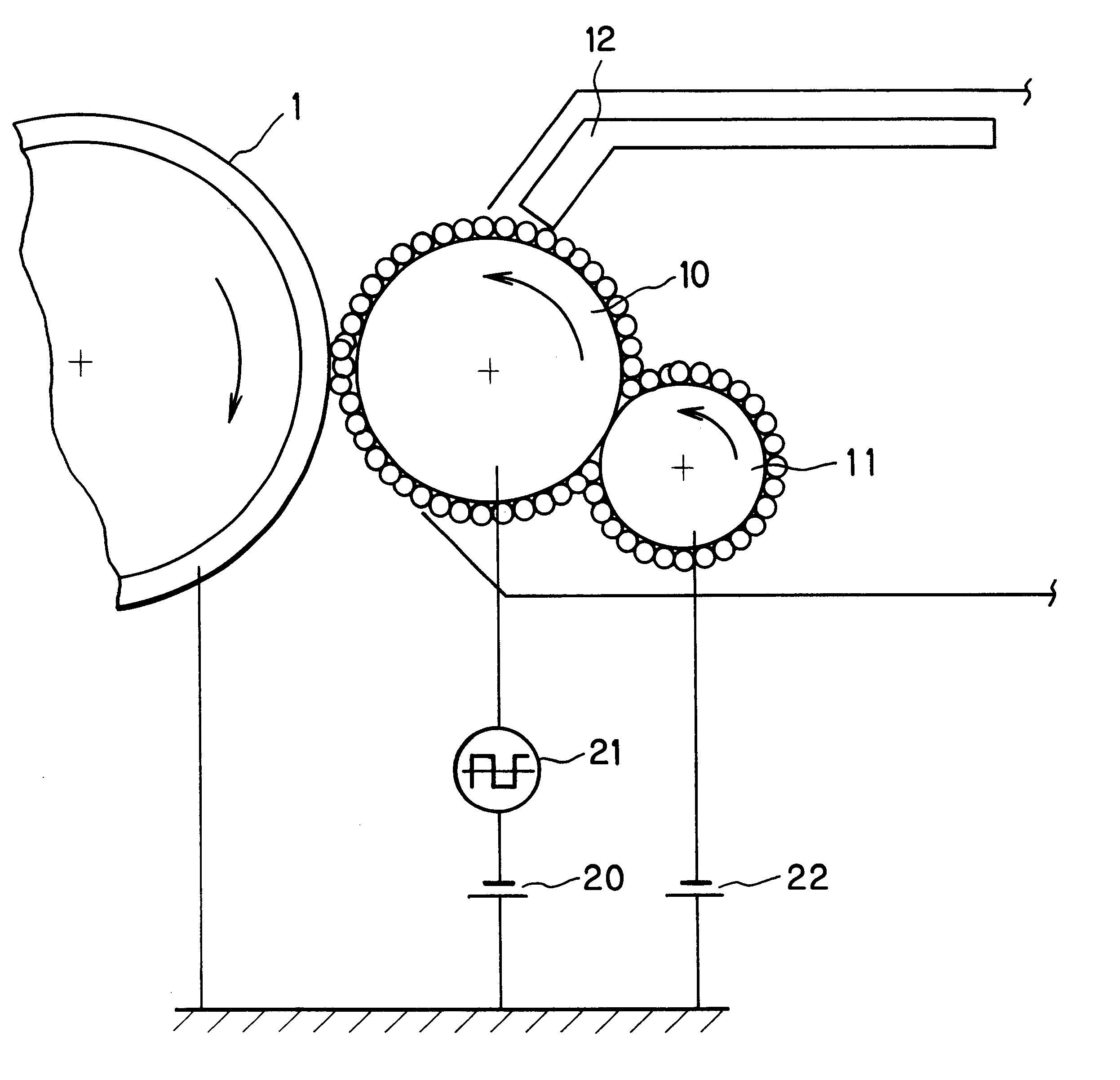
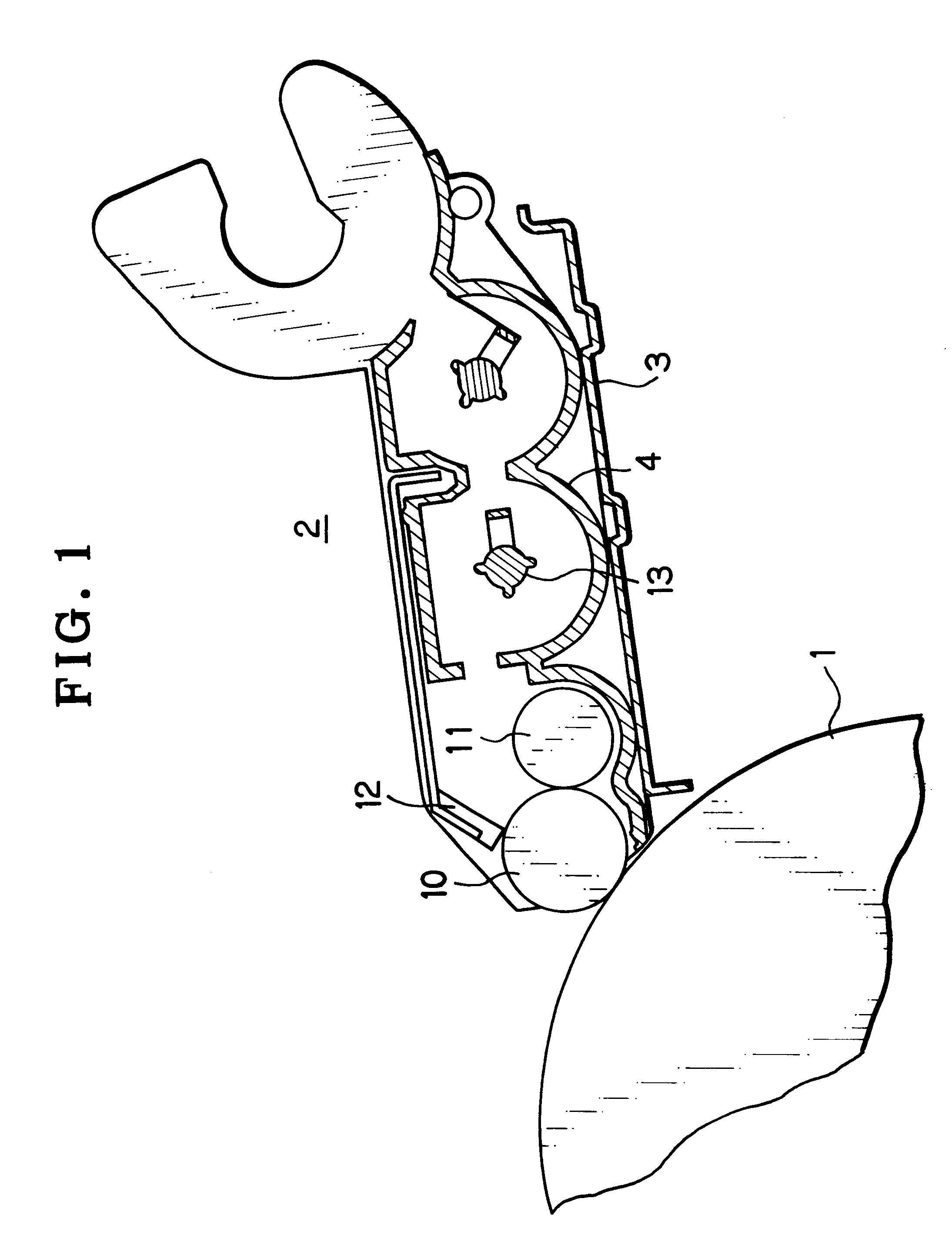
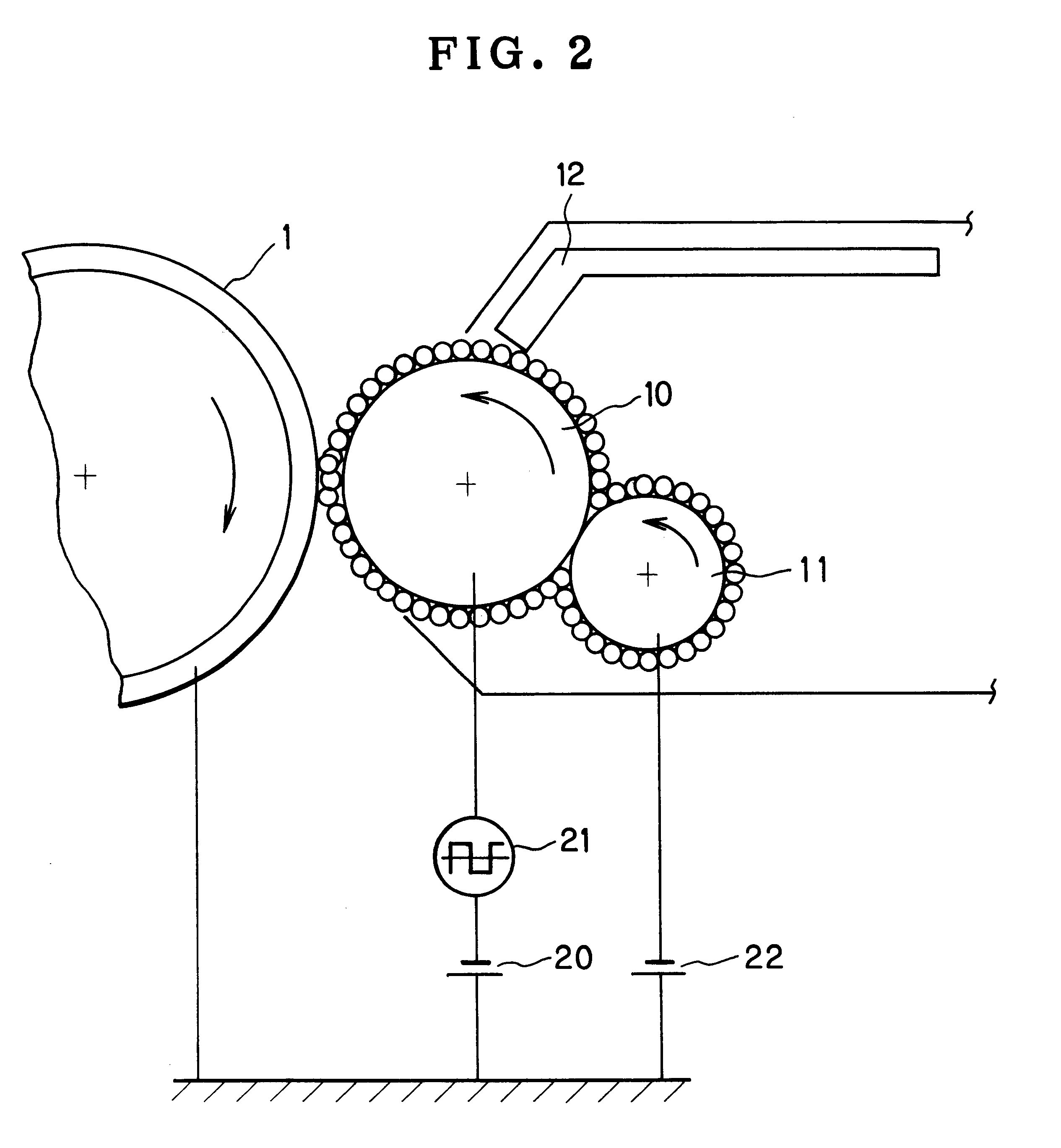
An embodiment of the present invention will be described below with reference to the accompanying drawings. FIG. 1 is a schematic view illustrating a developing unit used in the image forming apparatus according to the present invention. It should be noted that a full-color developing device has four developing units for yellow Y, magenta M, cyan C and black Bk; in FIG. 1, however, only one developing unit is shown.

In the figure, a photosensitive drum 1 serves as an electrostatic latent image carrier. The photosensitive drum 1 is an elastic roller with a photosensitive layer formed on the surface thereof. The photosensitive drum 1 is provided with a backup roller for supporting the elastic roller from the inside thereof at a position where the photosensitive drum surface contacts another member, e.g. a charging unit. A developing unit 2 is provided to face the photosensitive drum 1. The developing unit 2 has a frame 4 secured to a base 3. The frame 4 contains an agitator mechanism 1...


PUM


Abstract

An image forming apparatus has a latent image carrier on which a latent image is formed. A developer carrier conveys a one-component non-magnetic developer and develops the latent image either in close proximity to or in contact with the latent image carrier. A voltage application unit applies an AC-superimposed bias voltage to the developer carrier. A regulating member abuts against the developer carrier to regulate the thickness of the developer layer on the developer carrier. The regulating member has a semiconductive member provided at the distal end thereof to produce an electric potential difference between the semiconductive member and the developer carrier, to which the AC-superimposed bias voltage is applied, when regulating the thickness of the developer layer on the developer carrier, thereby forming a line-shaped uneven conveying surface. Thus, the occurrence of banding and longitudinal unevenness and stripes is prevented, and fogging and scattering are also prevented. Further, the occurrence of filming is prevented, thereby allowing formation of a uniform image free from density unevenness.

Description

1. Field of the InventionThe present invention relates to image forming apparatus for forming an image by developing an electrostatic latent image formed on a latent image carrier. More particularly, the present invention relates to an image forming apparatus designed to reduce the occurrence of density unevenness and stripe-shaped image defects in the formed image.2. Discussion of Related ArtConventionally, in the one-component non-magnetic development method, toner is supplied onto a developing roller, and the layer of toner on the developing roller is regulated with a regulating blade to a predetermined thickness to form a thin toner layer. Thereafter, a DC bias voltage or an AC bias voltage is applied to the developing roller either in or out of contact with a photosensitive member, thereby causing the toner to adhere to a latent image formed on the photosensitive member. Thus, the latent image is developed to form the desired image. In general, the developing roller in this typ...

Claims


Application Information

Patent Timeline
Patent Type & Authority Patents(United States)
IPC IPC(8): G03G15/08G03G15/06
CPCG03G15/065G03G15/0812G03G2215/0634
Inventor KIN, HIDENORIFUJITA, TORUTANAKA, KUNIAKI
Owner SEIKO EPSON CORP
Why Eureka
Try Eureka