Fan array fan section in air-handling systems

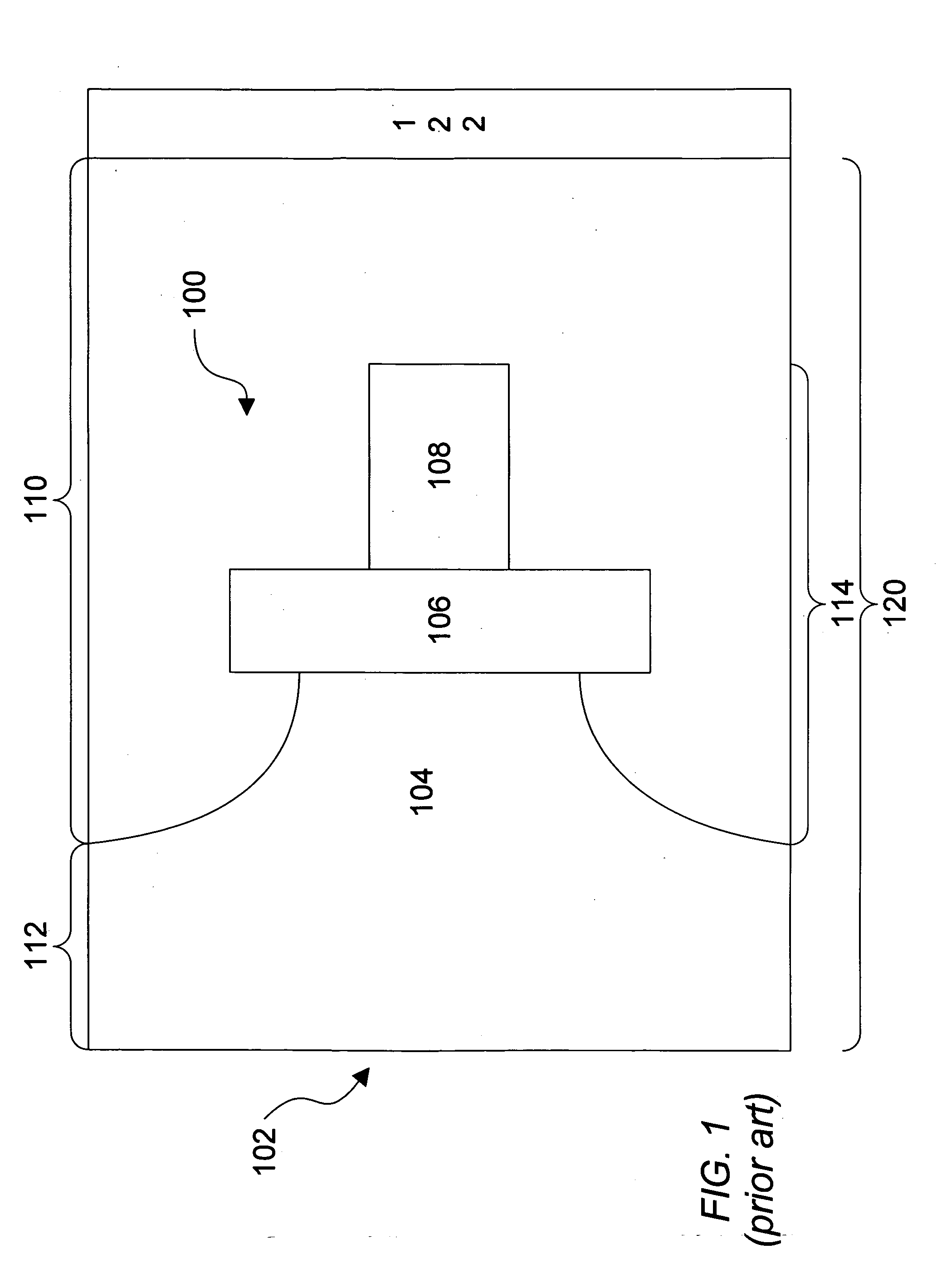
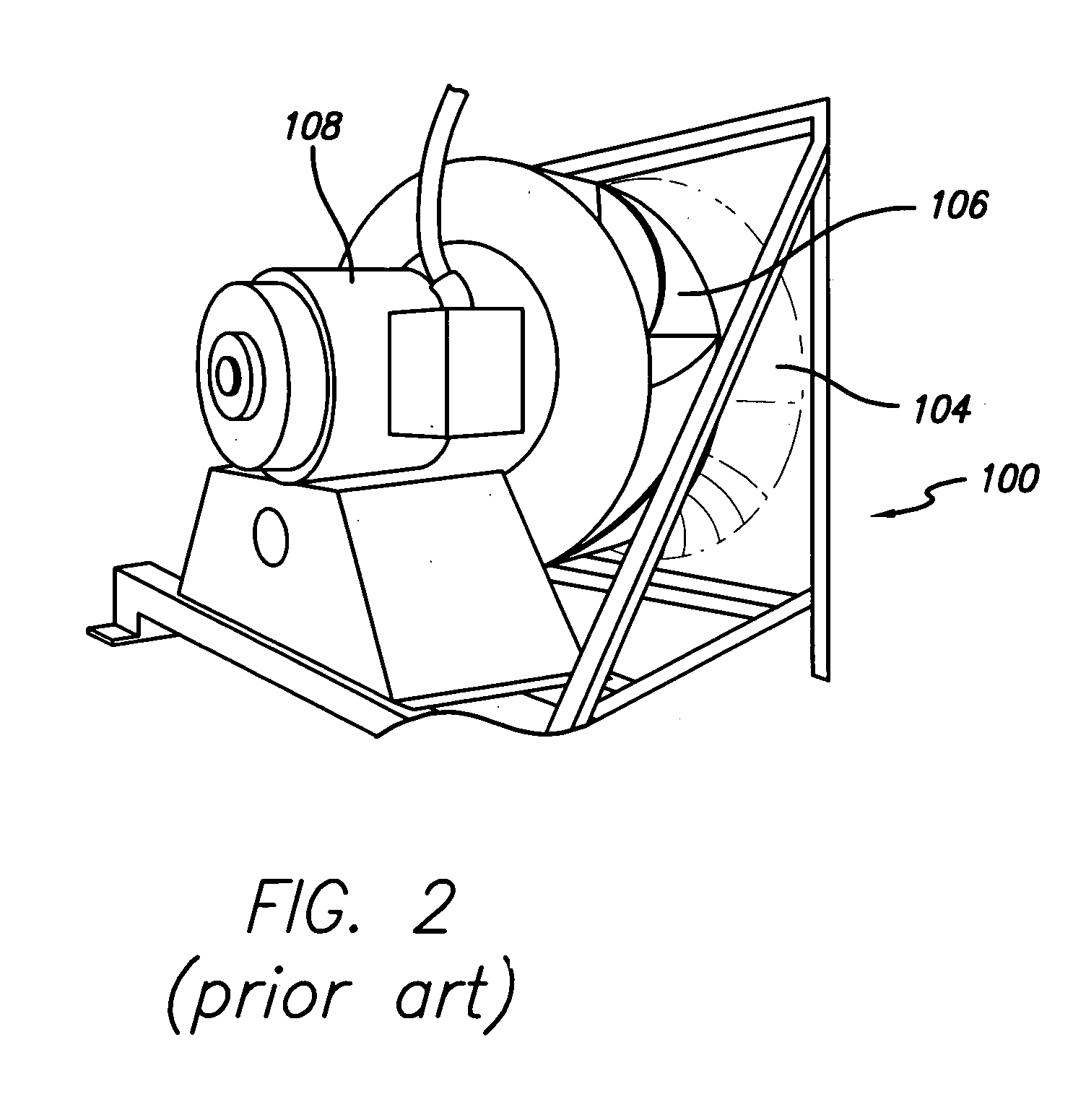
a fan array and air-handling system technology, applied in the direction of wind motors with perpendicular air flow, wind motors with parallel air flow, liquid fuel engine components, etc., can solve the problems of large air-handling compartment size b>102/b>, extremely large real estate (e.g. structure space), and high operating cost of single fan units b>100/b>

Active Publication Date: 2005-10-20
HUNTAIR +1
View PDF42 Cites 59 Cited by
  • Summary
  • Abstract
  • Description
  • Claims
  • Application Information

AI Technical Summary

Benefits of technology

[0019] The pre sent invention is directed to a fan array fan section in an air-handling system that includes a plurality of fan units arranged in a fan array and positioned within an air-handling compartment. One preferred embodiment may include an array controller programmed to operate the plurality o

Problems solved by technology

These prior art air-handling systems have many problems including the following exemplary problems: Because real estate (e.g. structure space) is extremely expensive, the larger size of the air-handling compartment 102 is extremely undesirable.
The single fan units 100 are expensive to produce and are generally custom produced for each job.
Single fan units 100 are expensive to operate.
Single fan units 100 are inefficient in that they only have optimal or peak efficiency over a small portion of their operating range.
The hig

Method used


Image

  • Fan array fan section in air-handling systems
  • Fan array fan section in air-handling systems
  • Fan array fan section in air-handling systems

Examples


Embodiment Construction

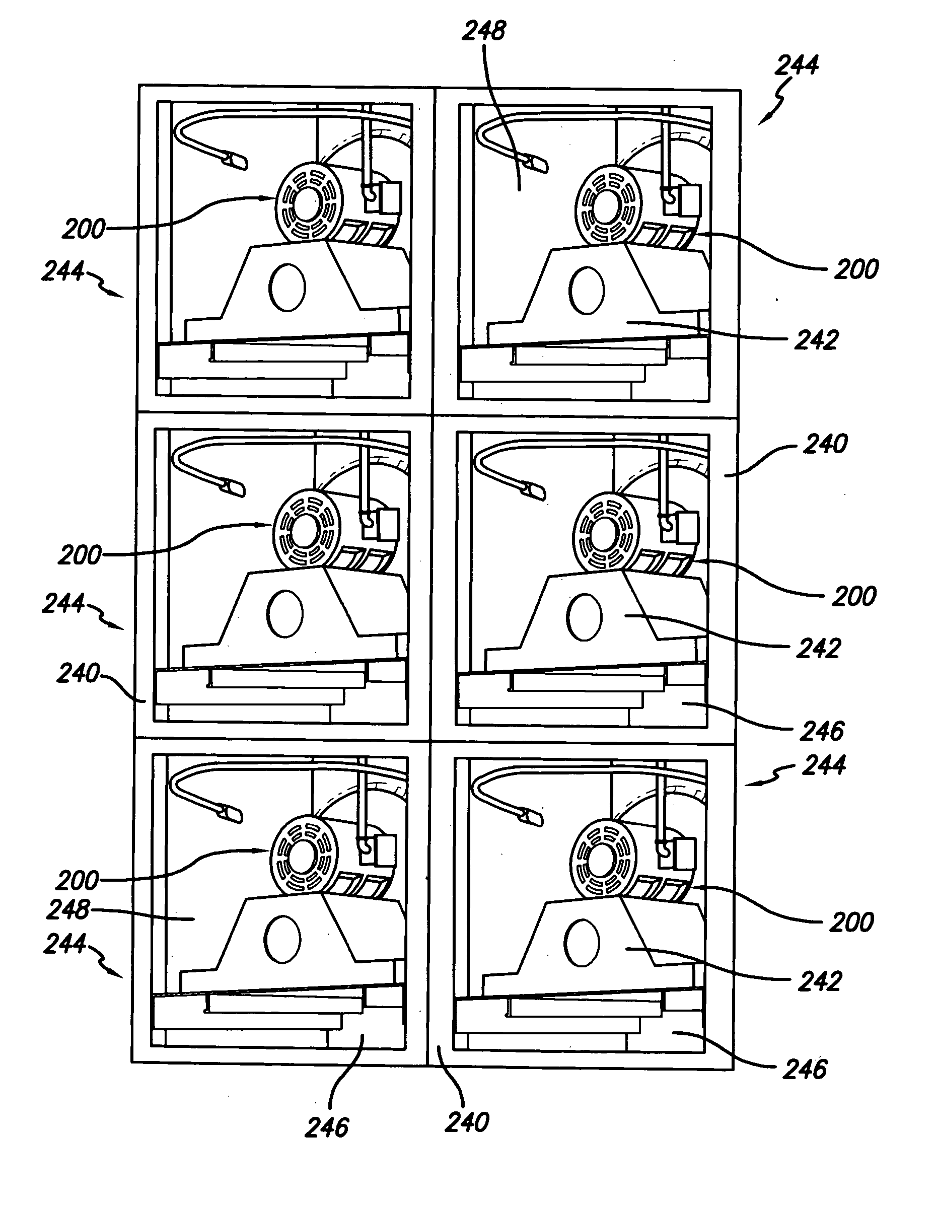
[0039] The present invention is directed to a fan array fan section in an air-handling system. As shown in FIGS. 3-12, the fan array fan section in the air-handling system uses a plurality of individual single fan units 200. In one preferred embodiment, the fan units 200 are arranged in a true array (FIGS. 4-8), but alternative embodiments may include, for example, alternative arrangements such as in a spaced pattern (FIG. 9), a checker board (FIG. 10), rows slightly offset (FIG. 11), or columns slightly offset (FIG. 12). As the present invention could be implemented with true arrays and / or alternative arrays, the term “array” is meant to be comprehensive.

[0040] The fan units 200 in the fan array of the present invention may be spaced as little as 20% of a fan wheel diameter. Optimum operating conditions for a closely arranged array may be found at distances as low as 30% to 60% of a fan wheel diameter. By closely spacing the fan units 200, more air may be moved in a smaller space....


PUM


Abstract

A fan array fan section in an air-handling system includes a plurality of fan units arranged in a fan array and positioned within an air-handling compartment. One preferred embodiment may include an array controller programmed to operate the plurality of fan units at peak efficiency. The plurality of fan units may be arranged in a true array configuration, a spaced pattern array configuration, a checker board array configuration, rows slightly offset array configuration, columns slightly offset array configuration, or a staggered array configuration.

Description

[0001] The present application is a continuation application of U.S. patent application Ser. No. 10 / 806,775, filed Mar. 22, 2004, and entitled FAN ARRAY FAN SECTION IN AIR-HANDLING SYSTEMS. U.S. patent application Ser. No. 10 / 806,775 is a nonprovisional application claiming the benefit under 35 USC Section 119(e) of U.S. Provisional Patent Application Ser. No. 60 / 554,702, filed Mar. 20, 2004, and entitled FAN ARRAY FAN SECTION IN AIR-HANDLING SYSTEMS. U.S. patent application Ser. No. 10 / 806,775 is a nonprovisional application claiming the benefit under 35 USC Section 119(e) of U.S. Provisional Patent Application Ser. No. 60 / 456,413, filed Mar. 20, 2003, and entitled FAN ARRAY FAN SECTION IN AIR-HANDLING SYSTEMS. U.S. patent application Ser. No. 10 / 806,775 is a continuation-in-part application of PCT Patent Application Serial Number PCT / US2004 / 008578, filed Mar. 19, 2004, and entitled FAN ARRAY FAN SECTION IN AIR-HANDLING SYSTEMS. The present application is based on and claims priori...

Claims


Application Information

Patent Timeline
IPC IPC(8): F04D25/16F24F7/06
CPCF04D25/166F24F7/06F04D19/002Y02B30/746F24F7/007F24F11/0079F04D27/004F24F11/77Y02B30/70F04D29/522F04D29/644F05D2270/023F05D2270/3061F04D27/0261F05D2270/03F24F11/74F04D29/664
Inventor HOPKINS, LAWRENCE G.
Owner HUNTAIR
Why Eureka
Try Eureka