Control scheme for multiple operating parameters in economized refrigerant system

a refrigerant system and control scheme technology, applied in refrigeration machines, lighting and heating apparatus, refrigeration safety arrangements, etc., can solve the problems of overall system efficiency, and low efficiency of evaporator performance, so as to reduce the amount of mass flow, and high mass flow

Inactive Publication Date: 2005-10-27
CARRIER CORP
View PDF18 Cites 34 Cited by
  • Summary
  • Abstract
  • Description
  • Claims
  • Application Information

AI Technical Summary

Benefits of technology

[0009] Another control strategy deals with maintaining discharge temperature within acceptable limits. The discharge temperature control is critical for compressor reliability (discharge temperature should not exceed a certain specified value). Since the normally cooler economizer flow is combined with the partially compressed main refrigerant flow (inside the compressor) cooling the latter, management of the economizer superheat by modulation of the expansion device to other than a preset value can effectively control compressor discharge temperature, particularly at high pressure ratio condition or minimum refrigerant flow conditions. Also during a high mass flow operation through a condenser, it can be advantageous to reduce the amount of mass flow through the economizer branch of the system. In this case, the reduction in the mass flow through the economizer branch of the system by modulation of the expansion valve would result in a drop in discharge pressure. The drop in the discharge pressure would lead to reduction of the discharge temperature.
[0010] Also, at the maximum load conditions (primarily occurring in high ambient temperature environments) compressor power can be limited (by the motor strength or compressor structural limitations). In such circumstances, while the system capacity is needed the most, nuisance shutdowns may occur as the system would trip on internal system protection and customers lose all cooling. In such circumstances, it would be desirable to unload the compressor before the shutdown would occur, and the economizer flow modulation approach offers such an opportunity. Continuous reduction in the economizer flow rate limits the required compressor power and prevents such shutdowns from happening in the most efficient manner (in comparison to other unloading techniques, such as switching between economized and non-economized modes of operation or bypassing a portion of the refrigerant flow to the compressor suction port), since a shutdown threshold can be easily determined. Additionally, power grid load during the peak load times can also be minimized.
[0011] Furthermore, the undesirable accumulation of ice on the evaporator coils can be minimized, under certain conditions, by increasing the saturated temperature of the refrigerant flowing through the evaporator coil. The increase in the evaporator coil temperature is achieved by gradually unloading the evaporator coil by decreasing the amount of subcooling entering the evaporator. The amount of subcooling in turn is decreased by gradually decreasing the amount of the expansion valve opening.
[0012] One advantage of the above control strategies is that they can easily be applied to tandem compressors operating in parallel with each other and sharing common condenser, evaporator and economizer heat exchanger. In this case, a common expansion valve located downstream of the economizer heat exchanger will control the amount of flow in the economizer line that is shared by both compressors.
[0013] System efficiency and life-cycle cost are the two essential ingredients of the unit design and acceptance ion the market. These parameters can be noticeably improved by the economizer modulation technique, since the number of start-stop compressor cycles is significantly reduced. As a result, temperature control, humidity control and compressor reliability are also improved.
[0014] It should be noted that all the techniques outlined above could be selectively implemented for each circuit in the multiple circuit system, which would enhance the overall unit operation and control.

Problems solved by technology

In the prior art, head pressure control has been achieved with some undesirable tradeoffs.
However, by modulating the amount of economizer flow, gradual adjustment of the head pressure can be achieved with minimal effect on evaporator performance and overall system efficiency.
In this case, the reduction in the mass flow through the economizer branch of the system by modulation of the expansion valve would result in a drop in discharge pressure.

Method used


Image

  • Control scheme for multiple operating parameters in economized refrigerant system
  • Control scheme for multiple operating parameters in economized refrigerant system
  • Control scheme for multiple operating parameters in economized refrigerant system

Examples


Embodiment Construction

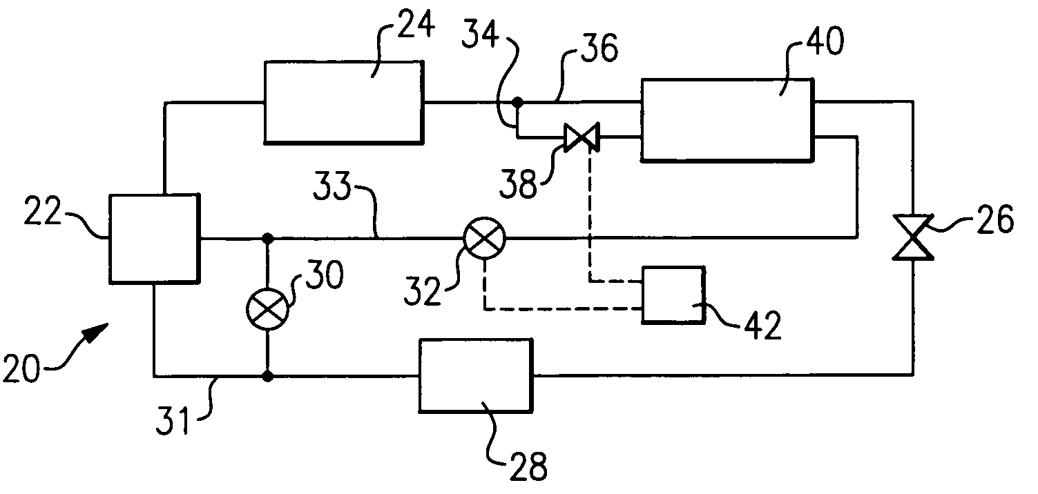
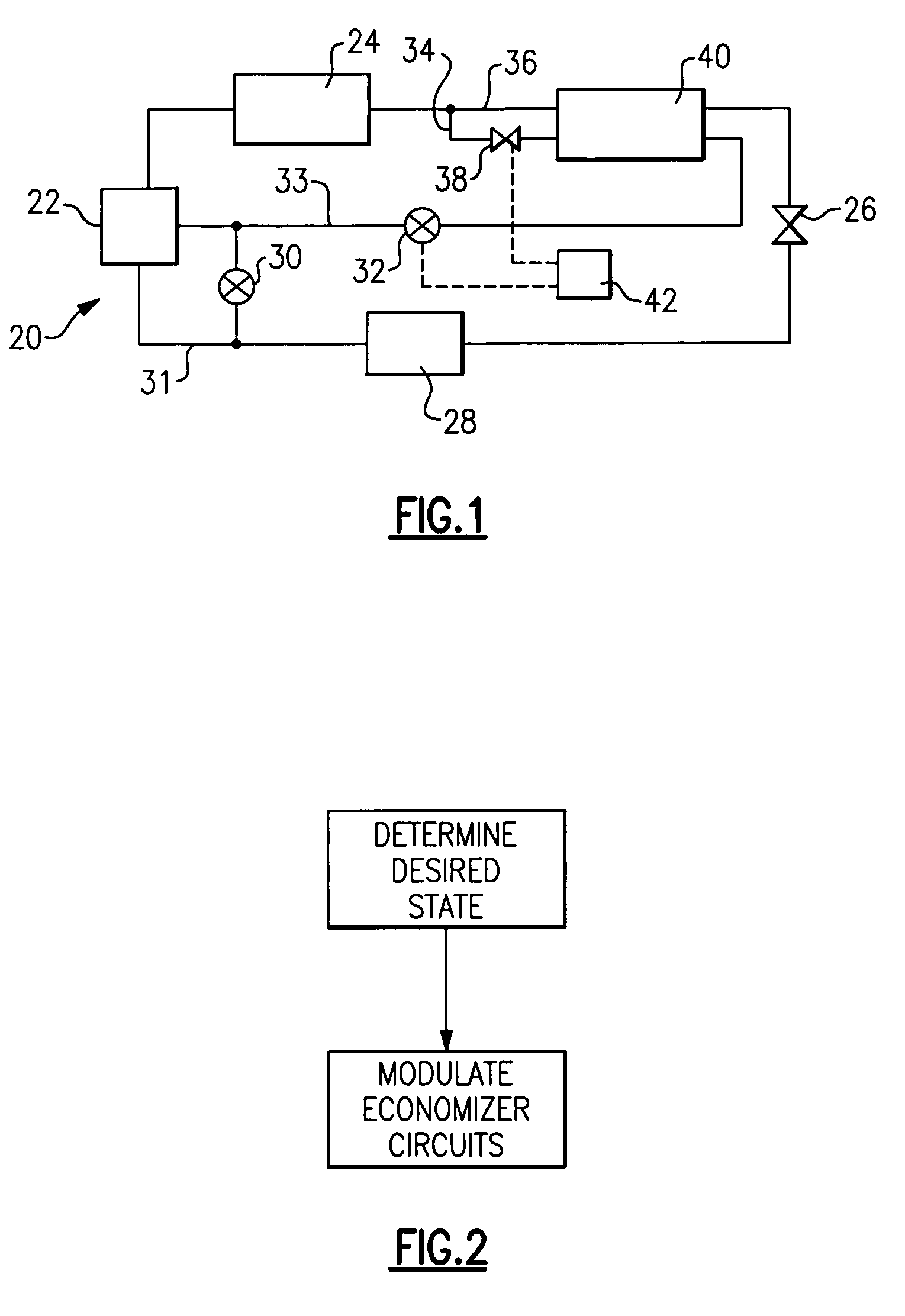
[0020]FIG. 1 shows a refrigerant cycle 20 having a compressor 22 delivering a refrigerant to a condenser 24. From condenser 24 the refrigerant passes to a main expansion device 26, and then to an evaporator 28. As is known, a bypass valve 30 may provide communication between a suction line 31, and an economizer return line 33. Economizer shutoff valve 32 may be placed on the return line 33. The refrigerant from the return line 33 enters the compressor 22 through intermediate port 44. A tap line 34 branches off from a main refrigerant flow in line 36 leading to the main expansion device 26. Tap line 34 passes through an auxiliary or economizer expansion device 38. The tapped refrigerant, after having passed through the expansion device or valve 38, passes through an economizer heat exchanger 40 along with the main refrigerant flow line 36. While the tapped and main refrigerant flows are illustrated, for simplicity, flowing in a common direction, it is preferred that the two flows hav...


PUM


Abstract

A refrigerant cycle is provided with an economizer circuit. The amount of refrigerant passing through the economizer circuit can be gradually modulated by an expansion device whose position can be easily adjusted from fully open to fully closed or disengaged. In the past, economizer circuits have either been fully engaged or fully disengaged. Modulation of economizer flow allows for variable capacity operation. This improves unit operating efficiency, minimizes unit cycling and prevents compressor overloading at extreme of operating conditions. It also allows for head pressure and discharge temperature control.

Description

BACKGROUND OF THE INVENTION [0001] This invention relates to the utilization of advantages offered by an economizer cycle to provide effective continuous and gradual variability in the control of multiple operating parameters in a refrigerant system. [0002] Refrigerant systems typically operate to provide heating or cooling for various applications. In a refrigerant cycle of a standard refrigerant system, a compressor compresses a refrigerant. The compressed refrigerant is delivered to a condenser, and from the condenser to an expansion valve. From the expansion valve the refrigerant is delivered to an evaporator, and then back to the compressor. [0003] One way to improve efficiency of modern refrigerant cycles is the use of an economizer cycle. In the economizer cycle, a portion of the refrigerant is tapped downstream of the condenser, and passes through an auxiliary expansion device. Passing this tapped refrigerant through the auxiliary expansion device cools the refrigerant. The ...

Claims


Application Information

Patent Timeline
Patent Type & Authority Applications(United States)
IPC IPC(8): F25B41/00F25B49/00F25B49/02
CPCF25B49/02F25B2400/075F25B2600/2509F25B2600/0261F25B2400/13
Inventor LIFSON, ALEXANDERTARAS, MICHAEL F.DOBMEIER, THOMAS J.
Owner CARRIER CORP
Why Eureka
Try Eureka