Heat and energy recovery ventilators and methods of use

a ventilator and energy recovery technology, applied in the field of can solve the problems of reducing the efficiency of ventilation, so as to improve the efficiency of ventilation and energy recovery. the effect of previous heat and energy recovery ventilators

Inactive Publication Date: 2005-10-27
STIRLING TECH INC +1
View PDF25 Cites 69 Cited by
  • Summary
  • Abstract
  • Description
  • Claims
  • Application Information

AI Technical Summary

Benefits of technology

[0009] Accordingly, the present invention is intended to address and obviate problems and short

Problems solved by technology

Some ventilators, however, are designed for use in existing heating, ventilating, and air conditioning (HVAC) systems that have sufficient air pressure to drive the countervailing streams, and may or may not also include blowers.
This conventional configuration makes heat and energy recovery ventilators relatively expensive, and/or excessively labor intensive to manufacture.
Unfortunately, the insulation alone does not always prevent condensation, and ultimately frost, from building up in the ventilator, particularly in extremely cold climates.
Frost build-up in the ventilator is undesirable because it lowers the efficiency and/or ventilation rate of a heat exchanger within the ventilator

Method used


Image

  • Heat and energy recovery ventilators and methods of use
  • Heat and energy recovery ventilators and methods of use
  • Heat and energy recovery ventilators and methods of use

Examples


Embodiment Construction

[0032] Reference will now be made in detail to various embodiments of the invention, examples of which are illustrated in the accompanying drawings, wherein like numerals indicate similar elements throughout the views.

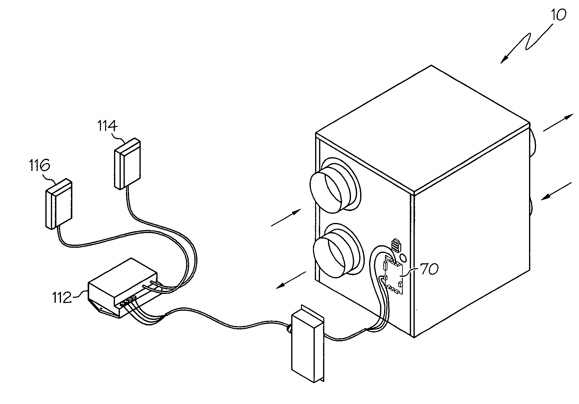
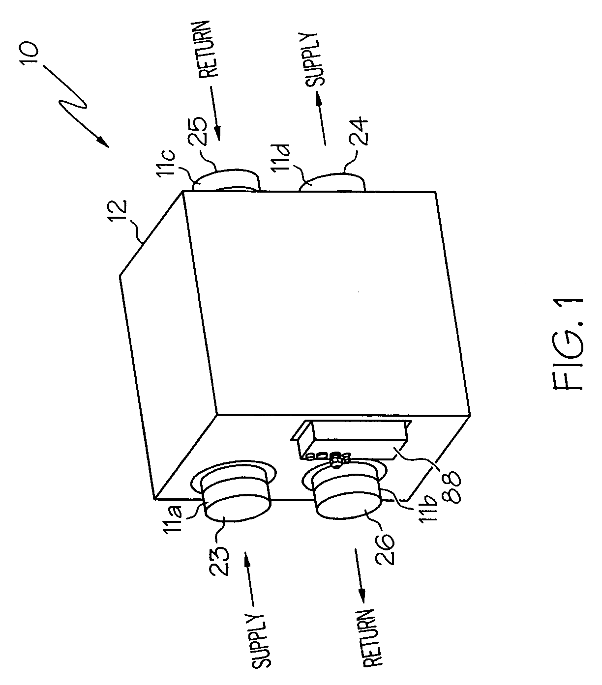
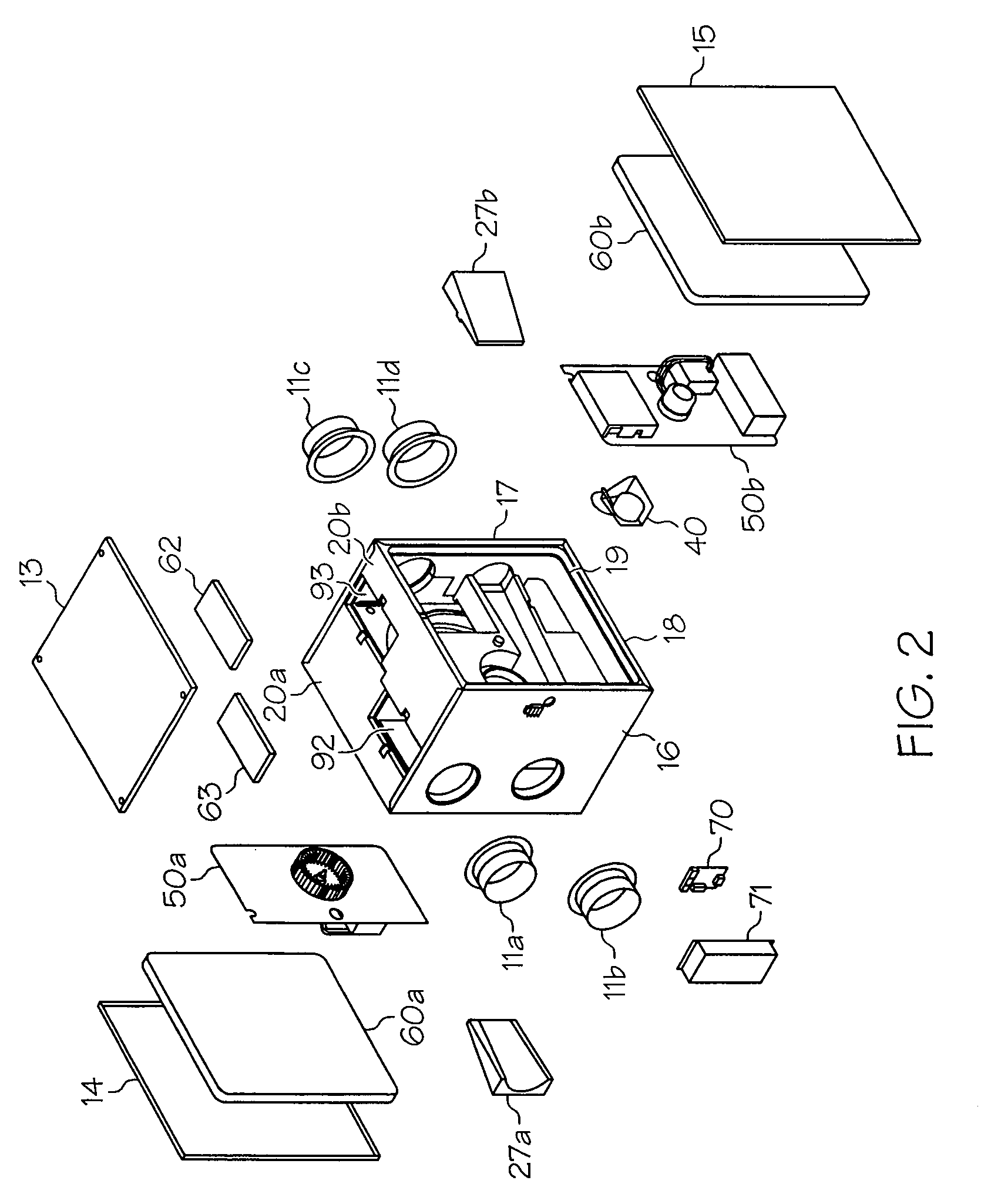
[0033] The present invention provides an improved, low cost energy recovery ventilator (hereinafter, “ERV”) for a structure such as a house, commercial or industrial building, dwelling, room, or any other enclosed space. An ERV transfers two different kinds of heat between a supply air stream and a return (e.g., exhaust) air stream, which are flowing through it. Sensible heat is measured with a thermometer and is the difference between the incoming (supply) and outgoing air temperature (return). The measurement of the sensible heat recovered is referred to as apparent sensible effectiveness and is expressed in a percent. Latent heat is the heat that was originally required to evaporate the moisture from a liquid into a gas and is an important consideration in the ener...


PUM


Abstract

An energy recovery ventilator and method for monitoring and maintaining an environmental condition inside a structure such as a house, building, or dwelling is provided. The ventilator may include a housing having mating halves of a molded polymeric material, first and second chambers disposed within the housing to convey separate first and second streams of air, a heat exchanger configured to intersect the first and second chambers, a first fan to circulate the first air stream through the first chamber, a second fan to circulate the second air stream through the second chamber, and a fan motor driving the first and second fans. The ventilator may also be configured to prevent frost build-up in or on the energy ventilator, to provide efficient cooling, and maintain one or more desired environmental conditions.

Description

CROSS REFERENCE TO RELATED APPLICATION [0001] This application claims the benefit of provisional application No. 60 / 564,474, filed Apr. 22, 2004.BACKGROUND OF THE INVENTION [0002] The present invention generally relates to heat and energy recovery ventilators. More particularly, the present invention relates to heat and energy recovery ventilators used to obtain thermally efficient ventilation of structures such as rooms, houses, buildings, and / or dwellings, and in particular, to those ventilators that include variable speed motors that are used to control a number of characteristics of air, heat, and humidity transfer through an enclosed space. [0003] Heat recovery ventilators are installed in residential, commercial, and industrial buildings to extract and remove heat from one air stream and transfer the heat to a second air stream, wherein energy recover ventilators are installed in these structures to extract and remove both heat and moisture from one air stream and transfer the...

Claims


Application Information

Patent Timeline
IPC IPC(8): F23L15/02F24F3/14F24F12/00F24F13/20
CPCF24F12/006F24F2203/1004F24F2203/1012Y10S165/909F24F2203/108F24F2203/1084Y02B30/563F24F2203/104Y02B30/56
Inventor CHAGNOT, CATHERINE J.MOROSKO, JASONSULFSTEDE, LOUIS
Owner STIRLING TECH INC
Why Eureka
Try Eureka