Forge welding method

a forging welding and pipe end technology, applied in welding/soldering/cutting articles, non-electric welding apparatus, manufacturing tools, etc., can solve the problems of grinding or machining operation which is difficult, expensive and difficult to achieve, and achieve the effect of minimizing the generation of upsets in the welding zon

Inactive Publication Date: 2005-10-27
TUBEFUSE APPL
View PDF38 Cites 5 Cited by
  • Summary
  • Abstract
  • Description
  • Claims
  • Application Information

AI Technical Summary

Benefits of technology

[0009] It is an object of the present invention to provide a method for forge w...

Problems solved by technology

Experiments have shown that forge welding techniques are capable to generate high quality metallurgical bonds between tubular ends, in particular if the pipe ends are flushed with a reducing flush gas mixture during the heating and/or welding operation, but that the red-hot pipe ends are generally deformed such that upsets are formed in the region of the welding zone...

Method used


Image

  • Forge welding method
  • Forge welding method
  • Forge welding method

Examples


Embodiment Construction

[0020] Preferred embodiments of the method according to the present invention will be described with reference to the accompanying drawings, in which:

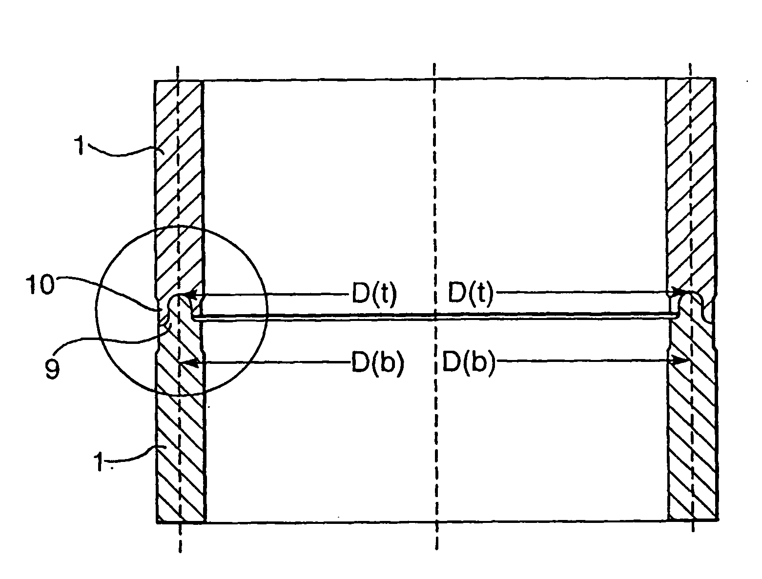
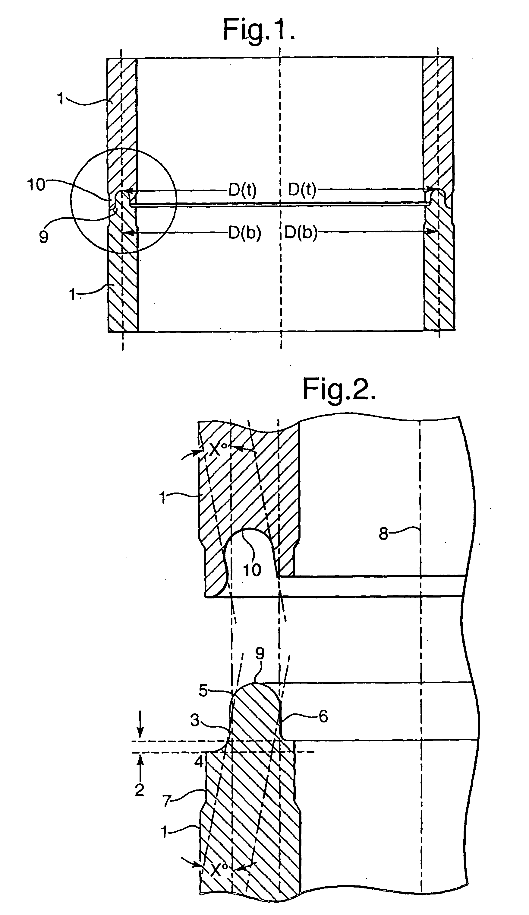
[0021]FIG. 1 shows a pair of concave and convex pipe ends that have been interconnected by the forge welding method according to the invention;

[0022]FIG. 2 shows how the concave and convex pipe ends are inwardly oriented at an inward sloping angle X which is selected such that the heated concave and convex pipe ends have a substantially longitudinal orientation;

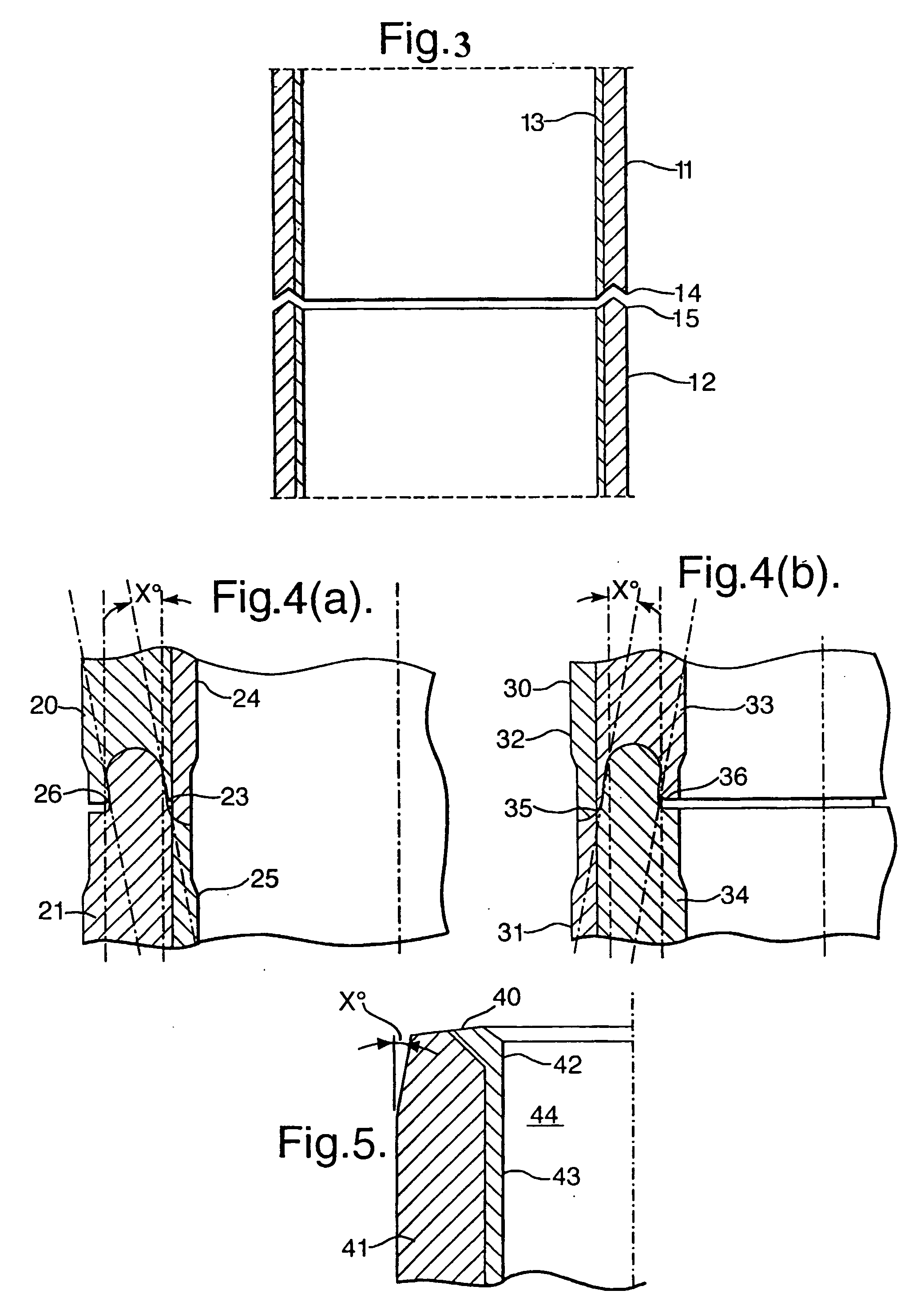
[0023]FIG. 3 is a longitudinal sectional view of a pair of cladded tubular ends just before they are joined by the forge welding method according to the invention;

[0024]FIG. 4a is a longitudinal sectional view of a pair of internally cladded tubular ends wherein one tubular end is concave and the other tubular end is convex;

[0025]FIG. 4b is a longitudinal sectional view of a pair of externally cladded tubular ends wherein one end is convex and the other end is concave; and ...


PUM

PropertyMeasurementUnit
Percent by volumeaaaaaaaaaa
Lengthaaaaaaaaaa

Abstract

The invention relates to a method for forge welding tubulars such that formation of upsets in the welding zone is minimized which involves shaping the tubular ends that are to be welded together into an inwardly sloping configuration such that when the tubular ends are heated during the forge welding process the heated tubular ends deform as a result of thermal expansion into a substantially longitudinally oriented cylindrical shape.

Description

BACKGROUND OF THE INVENTION [0001] The invention relates to a method for joining pipe ends by forge welding. [0002] Forge welding involves circumferential heating of the pipe ends that are to be joined and subsequently pressing the pipe ends together to form a metallurgical bond. [0003] A large variety of heating technologies may be used to make the pipe ends hot enough such that the metallurgical bond can be made. The heating techniques may involve electric, electromagnetic, induction, infrared, sparking and / or friction heating or combinations of these and other heating methods. [0004] When used in this specification the term forge welding is intended to encompass all techniques which involve circumferential heating of pipe ends and subsequent metallurgical bonding the heated pipe ends, including welding techniques that are generally known as amorphous bonding, diffusion bonding, friction welding, flash butt welding and / or thermodynamic welding. [0005] It is known from U.S. Pat. No...

Claims


Application Information

Patent Timeline
IPC IPC(8): B23K11/02B23K20/02B23K20/14B23K33/00
CPCB23K20/028B23K2203/16B23K33/006B23K20/14B23K2103/16B23K2103/172
Inventor MOE, PER THOMASMOE, PER HARALDDEN BOER, JOHANNIS JOSEPHUSCOLE, ANTHONY THOMASDIMITRIADIS, KLISTHENISHALMRAST, BJORNRABBEN, KJELL MAGNEZIJSLING, DJURRE HANS
Owner TUBEFUSE APPL
Why Eureka
Try Eureka