Declaration control apparatus and method for automotive vehicle

a technology of deceleration control and vehicle, applied in the direction of braking system, process and machine control, instruments, etc., can solve the problems of sudden and hard drive operation, change in vehicle behavior, driver discomfort, etc., to prevent vehicle overspeed, improve vehicle stability, and secure driver comfort

Inactive Publication Date: 2005-10-27
NISSAN MOTOR CO LTD
View PDF22 Cites 26 Cited by
  • Summary
  • Abstract
  • Description
  • Claims
  • Application Information

AI Technical Summary

Benefits of technology

[0005] The above-proposed vehicle deceleration control apparatuses are effective in preventing vehicle overspeed and improving vehicle stability so as to secure driver comfort. When these deceleration control apparatuses perform deceleration control under high lateral acceleration, however, there arises a vehicle load shift that can cause a change in vehicle behavior.
[0007] It is therefore an object of the present invention to provide a deceleration control apparatus and method for controlling deceleration of an automotive vehicle without causing a change in vehicle behavior under deceleration control.
[0010] According to a third aspect of the present invention, there is provided a deceleration control method for an automotive vehicle, comprising: causing deceleration of the vehicle in accordance with a traveling state of the vehicle; estimating a change in vehicle behavior occurring when the vehicle deceleration is caused; and controlling a braking force on each vehicle wheel so as to suppress the estimated vehicle behavior change.

Problems solved by technology

When these deceleration control apparatuses perform deceleration control under high lateral acceleration, however, there arises a vehicle load shift that can cause a change in vehicle behavior.
It is less likely that a vehicle behavior change will occur under the control of the above-proposed braking systems, but these braking system occasionally perform braking control (deceleration control) regardless of a driver's intention so that even a slight change in vehicle behavior leads to driver discomfort.
When the radius of the curved road is too small for the vehicle speed (i.e. when the vehicle comes into the curved road at overspeed), drive's steering operation becomes so abrupt and hard that the vehicle acceleration and yaw rate suddenly change.
In such a case, the vehicle behavior then becomes unstable at an earlier time.
The proposed braking systems may not be able to stabilize the vehicle behavior sufficiently by estimating the vehicle load shift based on the vehicle acceleration and then controlling the braking force distribution according the estimated load shift.

Method used


Image

  • Declaration control apparatus and method for automotive vehicle
  • Declaration control apparatus and method for automotive vehicle
  • Declaration control apparatus and method for automotive vehicle

Examples


third embodiment

[0020] The present invention will be described in detail by way of the following first, second and third embodiment, in which like parts and portions are designated by like reference numerals so as to omit repeated explanations thereof.

first embodiment

[0021] The first embodiment will be now explained below with reference to FIGS. 1 to 4, 5A and 5B.

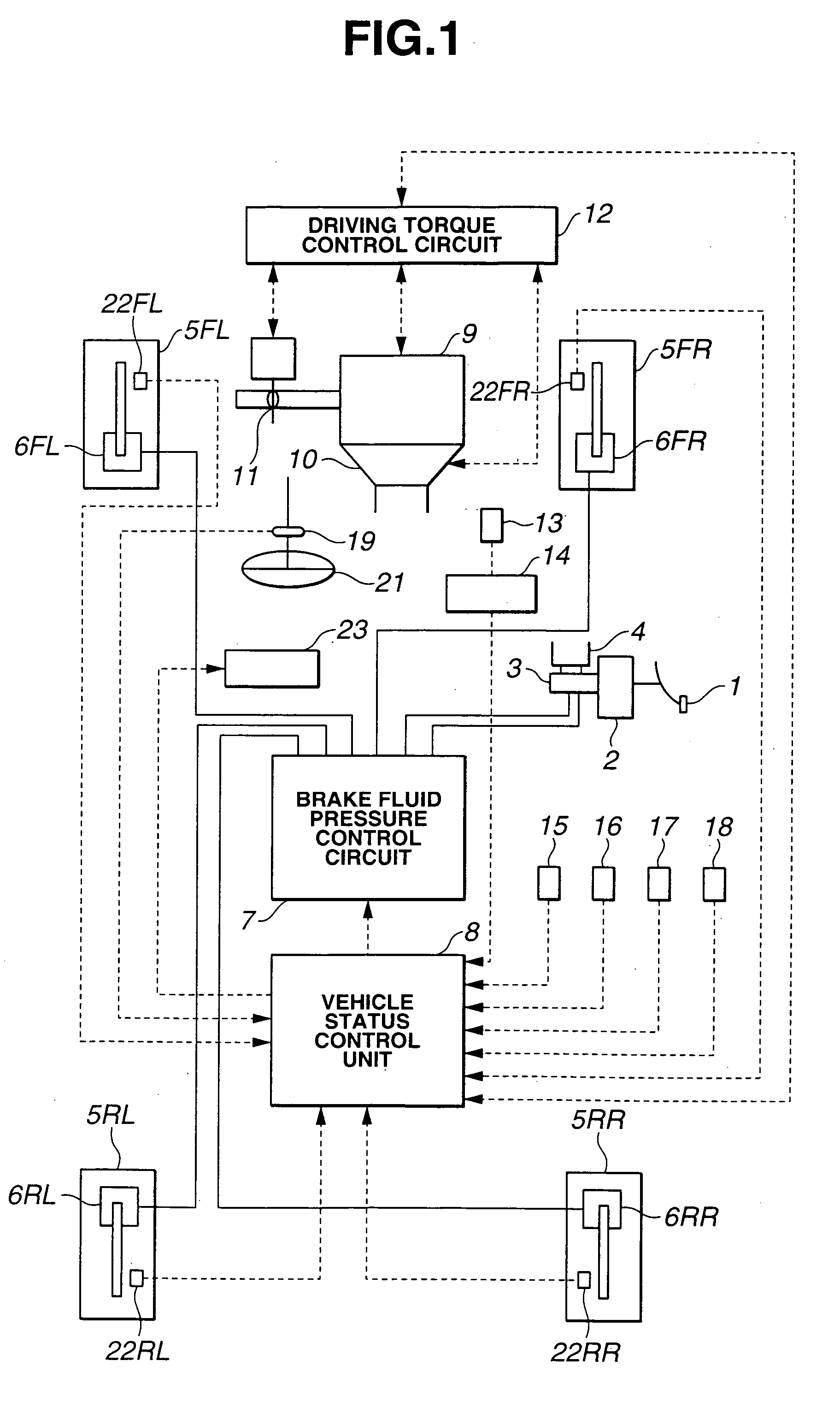
[0022] As shown in FIG. 1, the first embodiment refers to a rear-wheel-drive vehicle equipped with vehicle status control unit 8, a braking unit including brake pedal 1, booster 2, master cylinder 3, brake fluid reservoir 4 and brake fluid pressure control circuit 7, engine 9 with throttle 11, automatic transmission 10, a conventional differential gear and driving torque control circuit 12.

[0023] The braking unit is designed to control the braking force on each of front-left wheel 5FL, front-right wheel 5FR, rear-left wheel 5RL and rear-right wheel 5RR through brake fluid pressure regulation. Normally, a brake fluid is pressurized by master cylinder 3 in response to the depression of brake pedal 1 and fed to each of wheel cylinders 6FL, 6FR, 6RL and 6RR of vehicle wheels 5FL, 5FR, 5RL and 5RR. In the first embodiment, brake fluid pressure control circuit 7 is disposed between master cy...

second embodiment

[0081] The vehicle status is controlled as follows in the When the vehicle comes into a curved road, the vehicle speed V decreases with increase in the yaw rate φs.

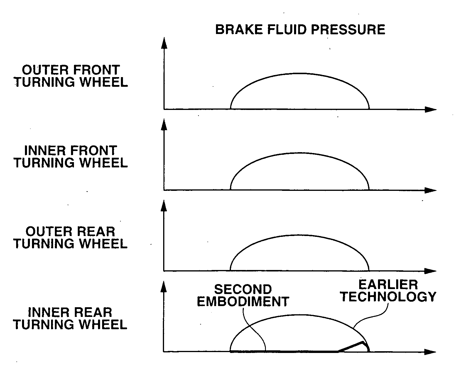
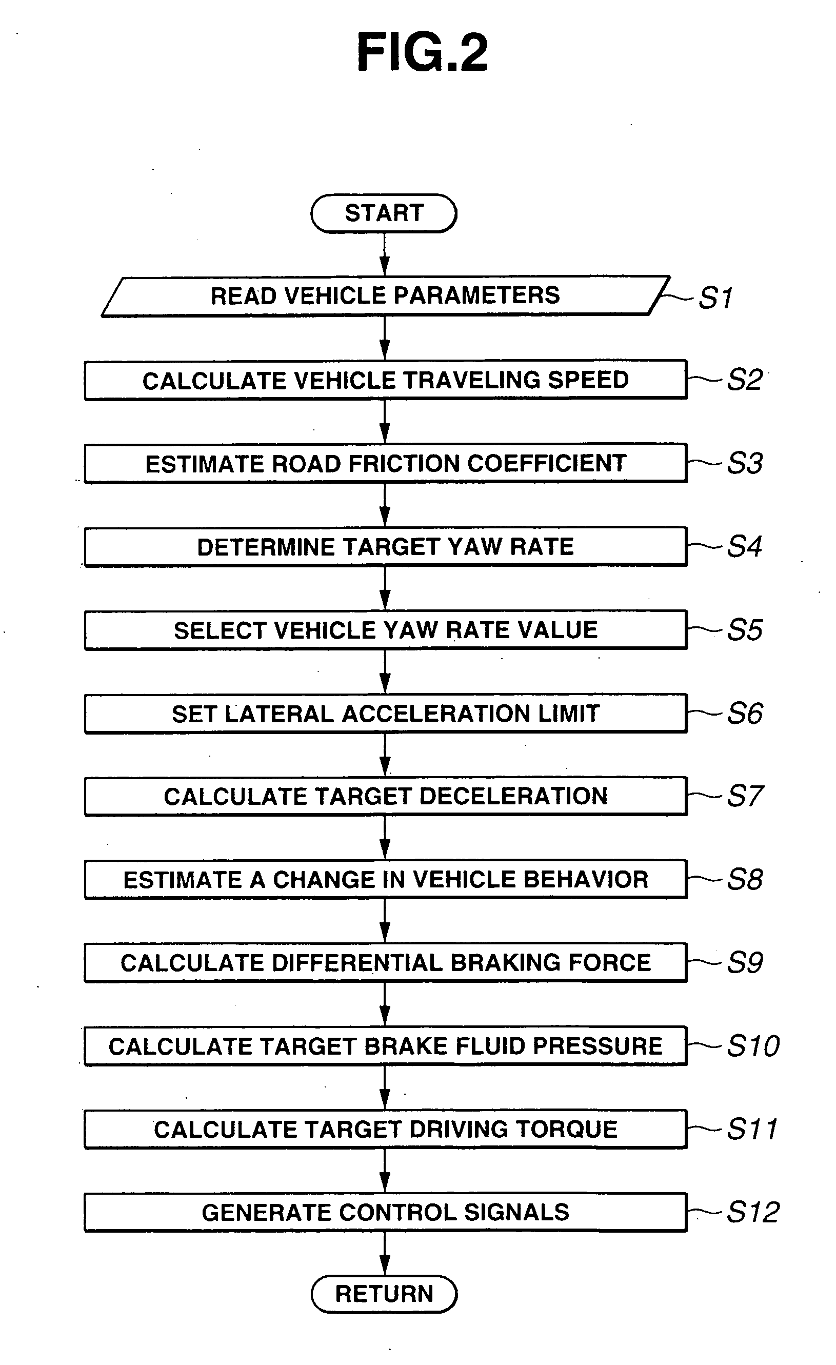
[0082] If the actual vehicle speed V is higher than the target vehicle speed Vs, the target deceleration Xgs becomes higher than zero (step S7). The deceleration control is thus performed. The vehicle turning behavior change Δφe is estimated (step S8) based on the current actual lateral acceleration Yg and the target deceleration Xgs with reference to the control map of FIG. 4. Then, the wheel limiting amount is calculated (step S9a). The target brake fluid pressure Pc is set so as to attain the target deceleration Xgs, and then, the target front-left-, front-right-, rear-left- and rear-right-wheel brake fluid pressures Psfl, Psfr, Psrl and Psrr so as to limit the braking force on inner rear wheel (i.e. rear-left wheel 5RR in this case) by the wheel limiting amount Pinlimt (step S10a) and thereby suppress the estimated v...


PUM


Abstract

There is provided a deceleration control apparatus for an automotive vehicle, which has a control unit including a deceleration control block that causes deceleration of the vehicle in accordance with a traveling state of the vehicle, an estimation block that estimates a change in vehicle behavior produced by causing the vehicle deceleration, and a suppression block that controls a braking force on each vehicle wheel so as to suppress the estimated vehicle behavior change.

Description

BACKGROUND OF THE INVENTION [0001] The present invention relates to a deceleration control apparatus and method for controlling deceleration of an automotive vehicle in accordance with a traveling state of the vehicle. [0002] Various deceleration control apparatuses have been proposed for automotive vehicles to prevent understeer during a vehicle turn. One type of vehicle deceleration control apparatus is configured to determine a vehicle safety speed according to the turning state of a vehicle and, if the actual vehicle speed exceeds the determined safety speed, automatically perform deceleration control on the vehicle in such a manner that the actual vehicle speed becomes lower than or equal to the safety speed. Japanese Patent No. 3133770 discloses another type of vehicle deceleration control apparatus that is configured to obtain information about the conditions of a curved road ahead of a vehicle from a navigation or infrastructure system and, if the vehicle speed is too high f...

Claims


Application Information

Patent Timeline
Patent Type & Authority Applications(United States)
IPC IPC(8): B60K31/00B60R16/02B60W10/04B60T7/12B60T8/172B60T8/1755B60T8/1763B60T8/1764B60T8/58B60W10/00B60W10/06B60W10/10B60W10/18B60W10/188B60W40/068F02D29/00F02D29/02
CPCB60T2201/08B60T8/17557
Inventor MATSUMOTO, SHINJISUZUKI, TATSUYANAKAMURA, MASAHIDE
Owner NISSAN MOTOR CO LTD
Why Eureka
Try Eureka