Deceleration control apparatus and method for automotive vehicle
a technology of deceleration control and control apparatus, which is applied in the direction of process and machine control, braking system, instruments, etc., can solve the problems of sudden and hard steering operation, change in vehicle behavior, and driver discomfort, so as to improve vehicle stability, prevent vehicle overspeed, and secure driver comfort
- Summary
- Abstract
- Description
- Claims
- Application Information
AI Technical Summary
Benefits of technology
Problems solved by technology
Method used
Image
Examples
third embodiment
[0020]The present invention will be described in detail by way of the following first, second and third embodiment, in which like parts and portions are designated by like reference numerals so as to omit repeated explanations thereof.
first embodiment
[0021]The first embodiment will be now explained below with reference to FIGS. 1 to 4, 5A and 5B.
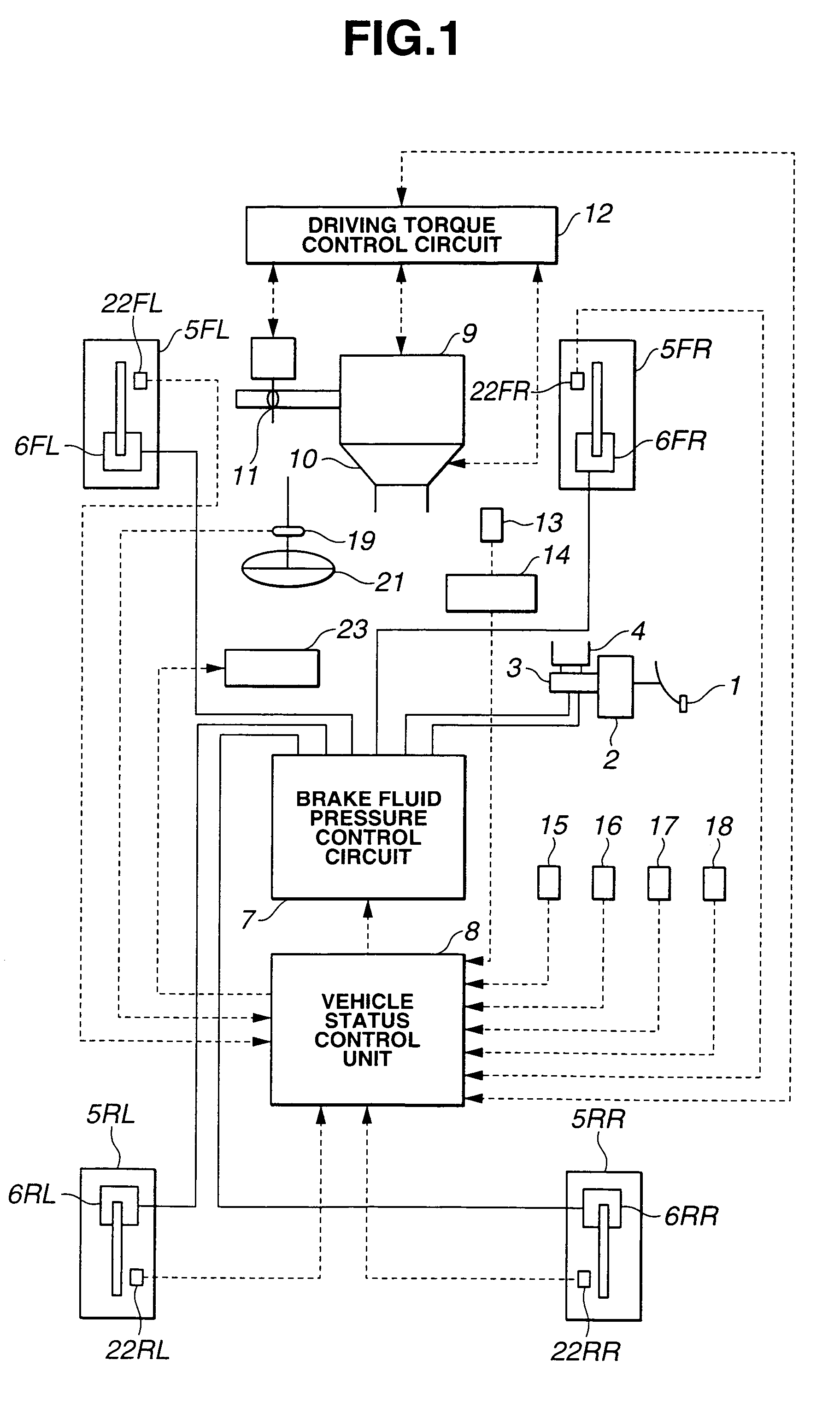
[0022]As shown in FIG. 1, the first embodiment refers to a rear-wheel-drive vehicle equipped with vehicle status control unit 8, a braking unit including brake pedal 1, booster 2, master cylinder 3, brake fluid reservoir 4 and brake fluid pressure control circuit 7, engine 9 with throttle 11, automatic transmission 10, a conventional differential gear and driving torque control circuit 12.
[0023]The braking unit is designed to control the braking force on each of front-left wheel 5FL, front-right wheel 5FR, rear-left wheel 5RL and rear-right wheel 5RR through brake fluid pressure regulation. Normally, a brake fluid is pressurized by master cylinder 3 in response to the depression of brake pedal 1 and fed to each of wheel cylinders 6FL, 6FR, 6RL and 6RR of vehicle wheels 5FL, 5FR, 5RL and 5RR. In the first embodiment, brake fluid pressure control circuit 7 is disposed between master cylind...
second embodiment
[0078]The vehicle status is controlled as follows in the When the vehicle comes into a curved road, the vehicle speed V decreases with increase in the yaw rate φs.
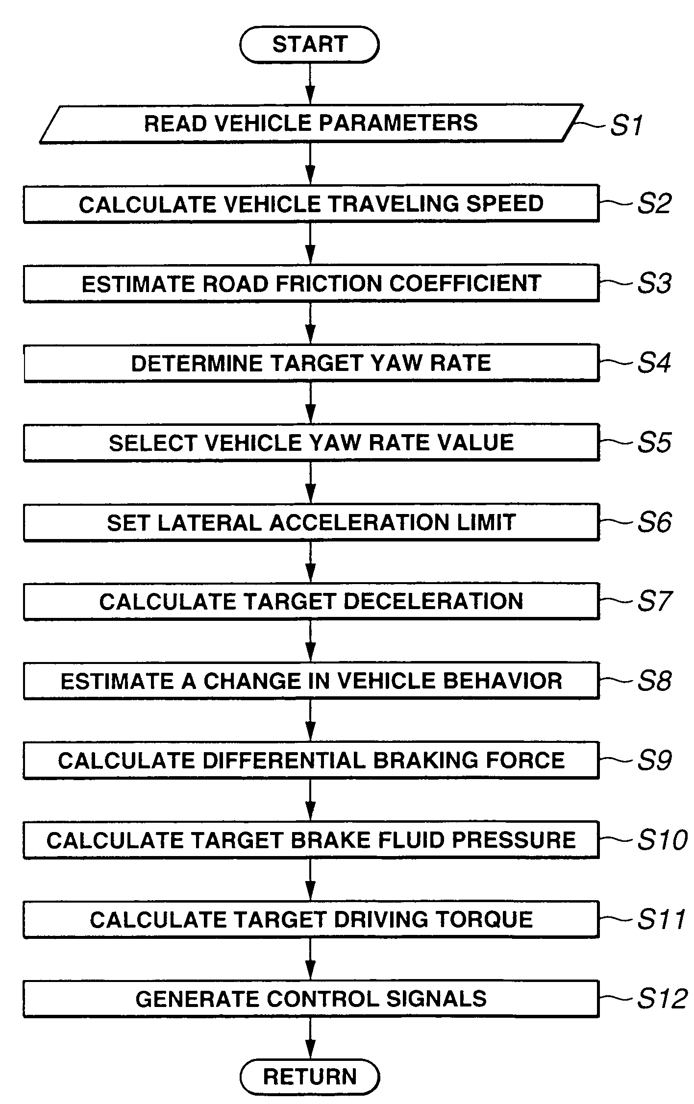
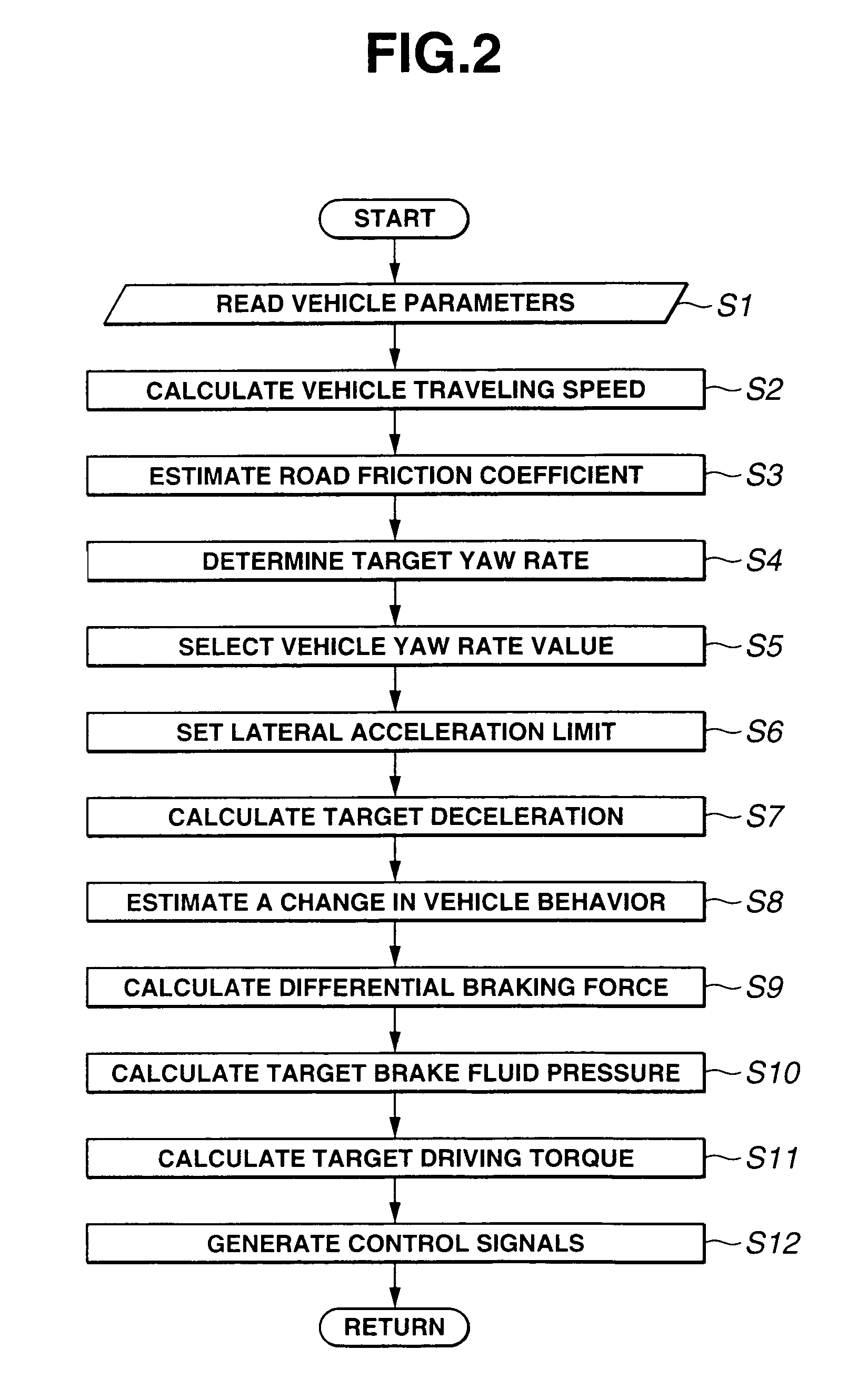
[0079]If the actual vehicle speed V is higher than the target vehicle speed Vs, the target deceleration Xgs becomes higher than zero (step S7). The deceleration control is thus performed. The vehicle turning behavior change Δφe is estimated (step S8) based on the current actual lateral acceleration Yg and the target deceleration Xgs with reference to the control map of FIG. 4. Then, the wheel limiting amount is calculated (step S9a). The target brake fluid pressure Pc is set so as to attain the target deceleration Xgs, and then, the target front-left-, front-right-, rear-left- and rear-right-wheel brake fluid pressures Psfl, Psfr, Psrl and Psrr so as to limit the braking force on inner rear wheel (i.e. rear-left wheel 5RR in this case) by the wheel limiting amount Pinlimt (step S10a) and thereby suppress the estimated veh...
PUM
 Abstract
Description
Claims
Application Information
 - R&D
- Intellectual Property
- Life Sciences
- Materials
- Tech Scout
- Unparalleled Data Quality
- Higher Quality Content
- 60% Fewer Hallucinations
Browse by: Latest US Patents, China's latest patents, Technical Efficacy Thesaurus, Application Domain, Technology Topic, Popular Technical Reports.
© 2025 PatSnap. All rights reserved.Legal|Privacy policy|Modern Slavery Act Transparency Statement|Sitemap|About US| Contact US: help@patsnap.com


