Variable antenna apparatus for a mobile terminal

a mobile terminal and antenna technology, applied in the field of mobile terminals, can solve the problems of difficult terminal carrying, easy damage, and weight of mobile terminals, and achieve the effect of convenient mobile terminal carrying

Active Publication Date: 2005-10-27
SAMSUNG ELECTRONICS CO LTD
View PDF8 Cites 3 Cited by
  • Summary
  • Abstract
  • Description
  • Claims
  • Application Information

AI Technical Summary

Benefits of technology

[0013] Accordingly, the present invention has been designed to solve the above and other problems occurring in the prior art, and a first object of the present invention is to provide a variable antenna apparatus for a mobile terminal, which enables various terminal designs to more conveniently carry the mobile terminal.

Problems solved by technology

Such mobile terminals have a current tendency to be lightweight and compact in size.
However, an antenna apparatus protruding out of a terminal, such as antenna apparatus 19, restricts a design of the mobile terminals and may make it difficult to carry the terminal.
Further, because the antenna apparatus is exposed to the outside, it may be easily damaged when any external impact is applied thereto or when the mobile terminal is dropped.
However, an antenna gain of the internal antenna may be reduced due to electromagnetic interference between the internal antenna and circuit devices, such as a radio frequency (RF) board of the terminal, and due to interference from a structure, such as a terminal housing.
Consequently, it is difficult to ensure good quality of service (QoS) of the mobile terminal.

Method used


Image

  • Variable antenna apparatus for a mobile terminal
  • Variable antenna apparatus for a mobile terminal
  • Variable antenna apparatus for a mobile terminal

Examples


Embodiment Construction

[0023] Preferred embodiments of the present invention will be described in detail herein below with reference to the accompanying drawings. In the accompanying drawings, the same or similar components are designated by the same reference numerals although they are shown in different drawings. Additionally, in the following description of the present invention, a detailed description of known functions and configurations incorporated herein will be omitted when it may obscure the subject matter of the present invention.

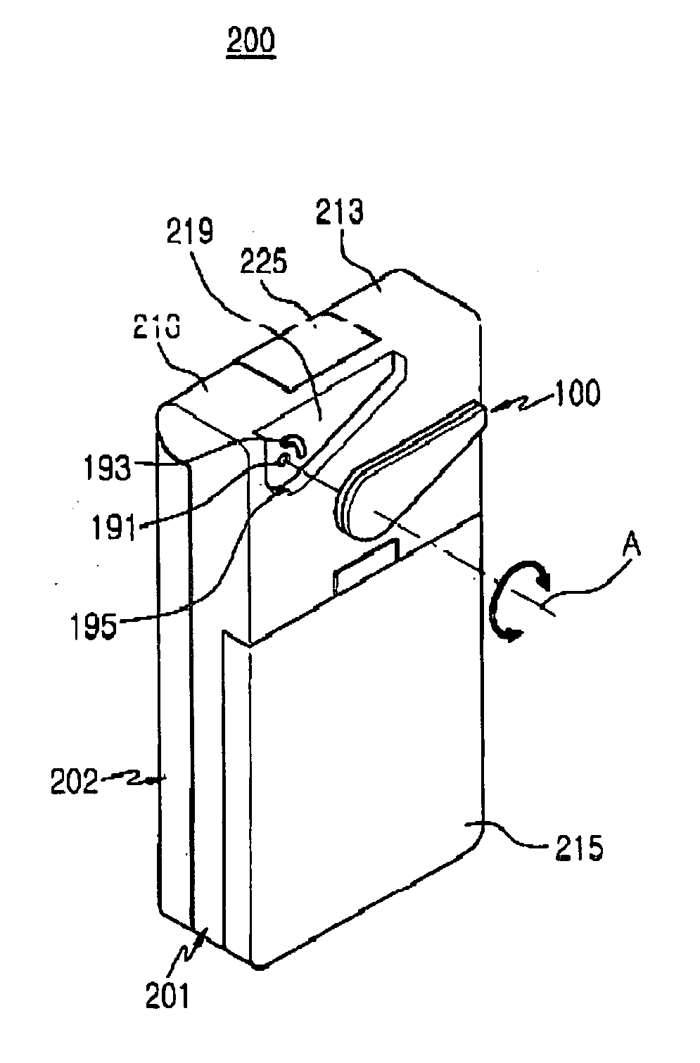
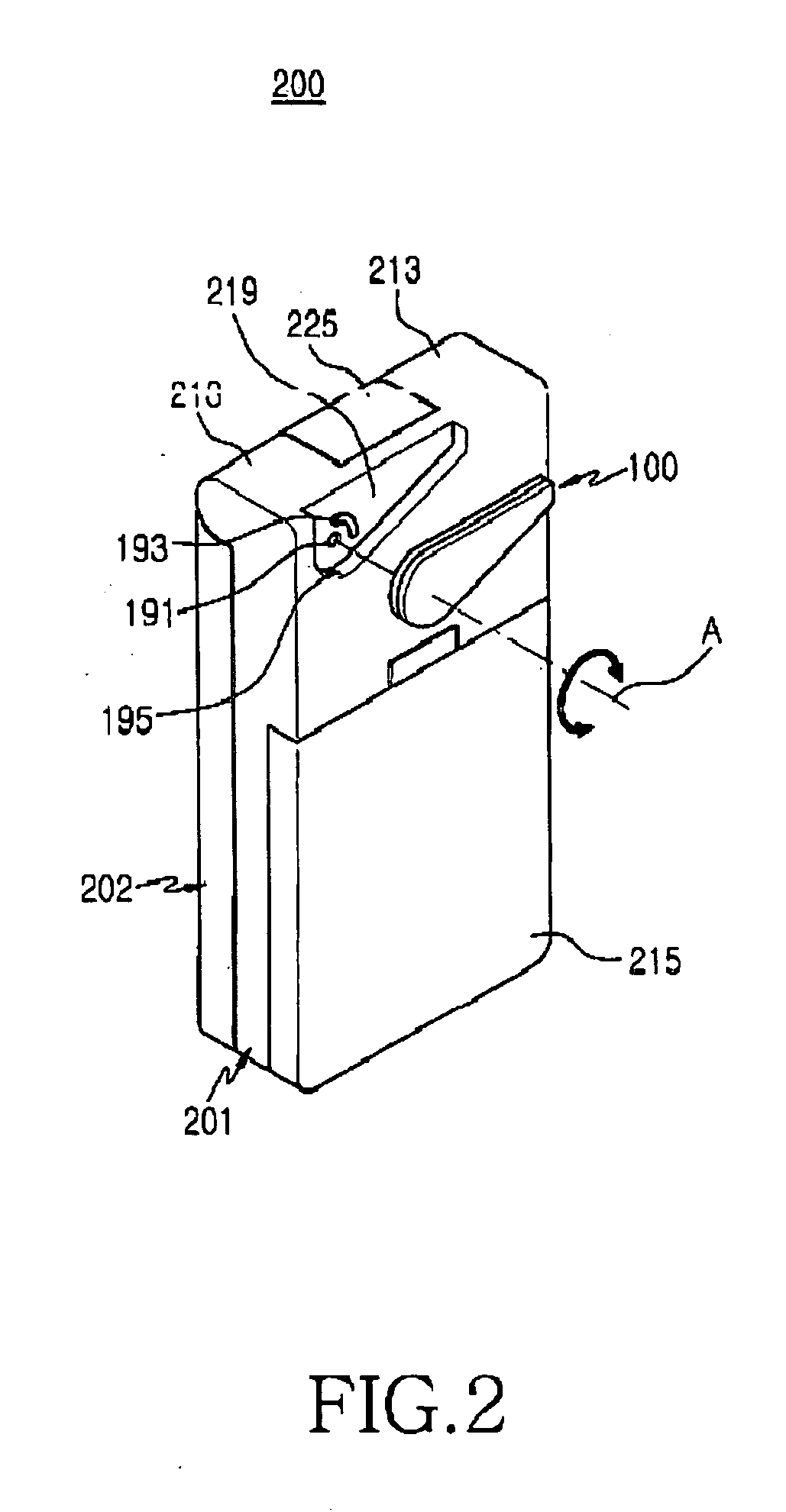
[0024]FIG. 2 illustrates a mobile terminal 200 including a variable antenna apparatus 100 according to a preferred embodiment of the present invention. As illustrated in FIG. 2, the mobile terminal 200 is a folder-type terminal including a body 201 and a folder 202 rotatably coupled with the body 201. A battery 215 is provided at a rear side of the body 201. Although not illustrated, a keypad and a signal transmitting part are installed on the body 201, and a main dis...


PUM


Abstract

A variable antenna apparatus for a mobile terminal. The variable antenna apparatus includes a radiation component that is rotatably coupled with the mobile terminal, a feeding component that is adjacent to a first end part of the radiation component and electrically connected to a radio frequency board of the mobile terminal. A grounding component is adjacent to the first end part of the radiation component and selectively connected to a ground of the radio frequency board as the radiation component is rotated. The antenna apparatus is accommodated in a terminal so that it is possible to conveniently carry the terminal, and the antenna is rotatably protruded from the terminal during a telephone call, such that appropriate antenna gain is achieved.

Description

PRIORITY [0001] This application claims priority to an application entitled “Variable Antenna Apparatus for Mobile Terminal” filed in the Korean Intellectual Property Office on Apr. 22, 2004 and assigned Serial No. 2004-27728, the contents of which are hereby incorporated by reference. BACKGROUND OF THE INVENTION [0002] 1. Field of the Invention [0003] The present invention relates generally to a mobile terminal, and more particularly to an antenna apparatus of a mobile terminal. [0004] 2. Description of the Related Art [0005] Conventionally, the term “mobile terminal” refers to mobile electronic device capable of communication. Such mobile terminals have a current tendency to be lightweight and compact in size. Also, mobile terminals provide many functions, such as multimedia and Internet services. [0006] Additionally, mobile terminals are being produced with various and distinguished designs, such as rotary-type terminals capable of inversely rotating a housing equipped with a dis...

Claims


Application Information

Patent Timeline
Patent Type & Authority Applications(United States)
IPC IPC(8): H01Q1/24H01Q9/04
CPCH01Q1/084H01Q9/0421H01Q1/244A01K47/02A01K47/04
Inventor KIM, DONG-HWANCHO, BYUNG-DUCKCHOI, WAN-JIN
Owner SAMSUNG ELECTRONICS CO LTD
Why Eureka
Try Eureka