Method for operating a matrix converter and matrix converter for implementing the method

a technology of matrix converter and matrix converter, which is applied in the direction of single ac network with different frequencies, power distribution line transmission, electric power transfer ac network, etc., can solve the problems of increasing the rotary speed of the turbine, occupying reactive power, and increasing the size and cost of the turbin

Active Publication Date: 2005-10-27
GENERAL ELECTRIC TECH GMBH
View PDF7 Cites 21 Cited by
  • Summary
  • Abstract
  • Description
  • Claims
  • Application Information

AI Technical Summary

Benefits of technology

[0033] The invention includes operating the matrix converter in “reverse mode”, so to speak, as a cycloconverter. The fact that this is possible quite easily and without any modification of the hardware of the matrix converter by simply changing of the mode of operation of the matrix converter and by providing means grouping the m phases of the generator in corresponding subgroups, is unexpected and makes it possible to use such mode of operation of a matrix converter for starting up a gas turbine unit by using the generator as motor and the mains as power source.
[0034] According to a first preferred embodiment of the present invention, the matrix converter, when being operated to convert energy from the generator to the load, only allows to control frequency but not voltage. In particular in this case, where such matrix converters cannot be used in a reverse mode for start-up of a gas turbine unit directly due to the “constant V / f rule” necessitating the control of voltage at least within the first part of the start-up of the generator which behaves like an electrical machine, the switching between the two modes is advantageous.

Problems solved by technology

In power generation, at a specified output, an increase of the rotary speed of a turbine is typically associated with a decrease in size and costs.
As the output increases, the use of gearing arrangements becomes increasingly difficult for safety reasons.
The use of a gearing arrangement is typically associated with the following disadvantages: a fixed transmission ratio; a noise level above 100 db for 40 MW, and above 115 db for 70 MW; mechanical losses irrespective of the particular load; and exacting requirements with regard to cooling and lubrication with oil.
A reduction of the losses would above all have a bearing on investment costs because cooling accounts for a substantial part of the total costs of the converter.
However, induction motors for example, take up reactive power.
In this case there is forced commutation and thus there are increased losses.
This results in strongly pulsating torques and large additional losses in the electrical machine which can lead to deterioration of the machine.
However, the use of cyclo-converters limits the achievable frequency range to 0-⅓ of the input frequency.
Due to imbalanced operation, exceeding the ⅓ limit results in overdimensioning up to a factor of 3.
This provides the option of establishing any desired connections between the input phases and the output phases; however at the same time it has the disadvantage in that certain switching states of the matrix must not be allowed since otherwise for example a short circuit would result.
This considerably increases the switching expenditure.
However, this mode of operation allowing a cheap and reliable control of the matrix converter can only be used to control frequency but not to control the voltage.

Method used


Image

  • Method for operating a matrix converter and matrix converter for implementing the method
  • Method for operating a matrix converter and matrix converter for implementing the method
  • Method for operating a matrix converter and matrix converter for implementing the method

Examples


Embodiment Construction

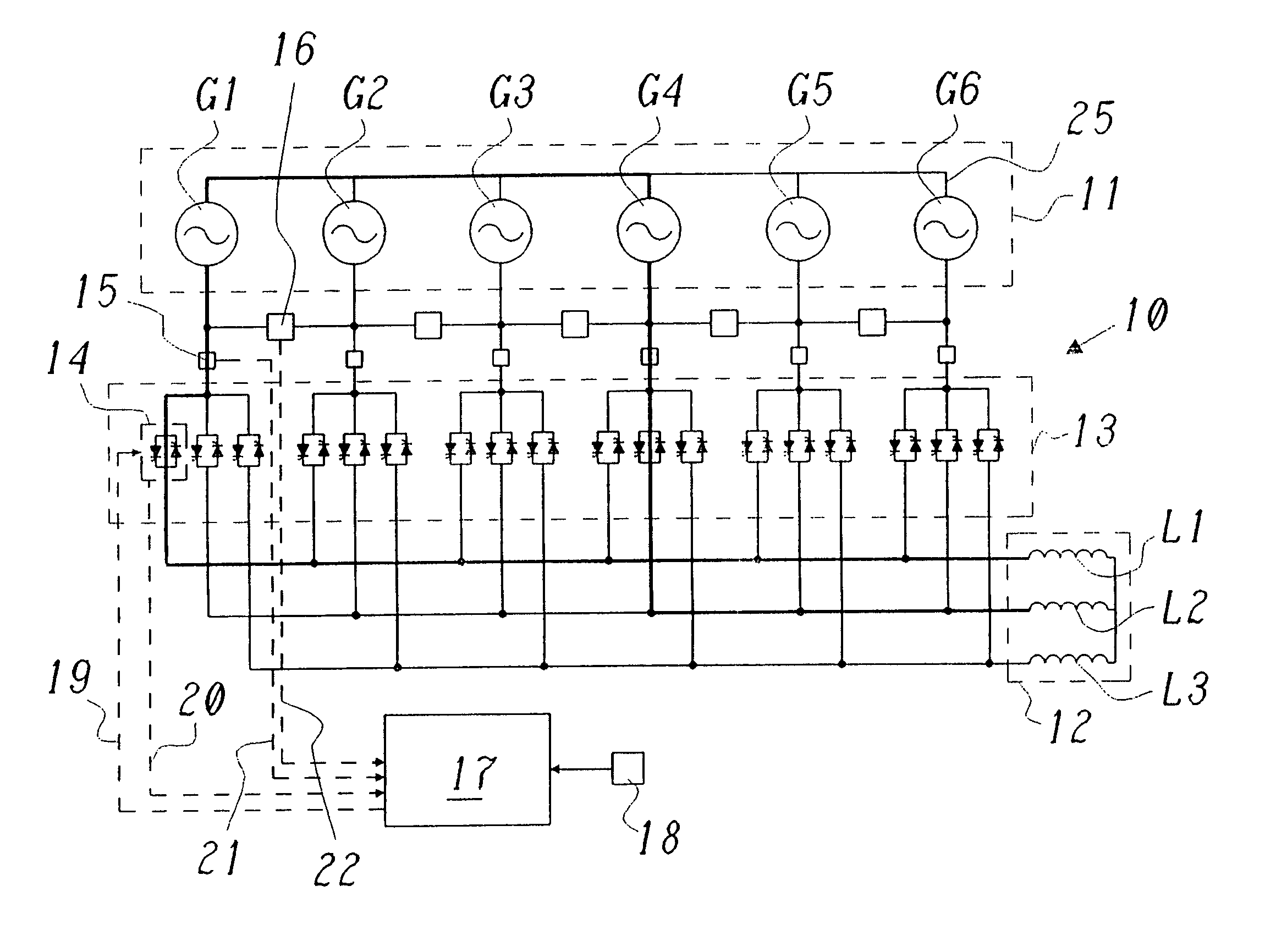
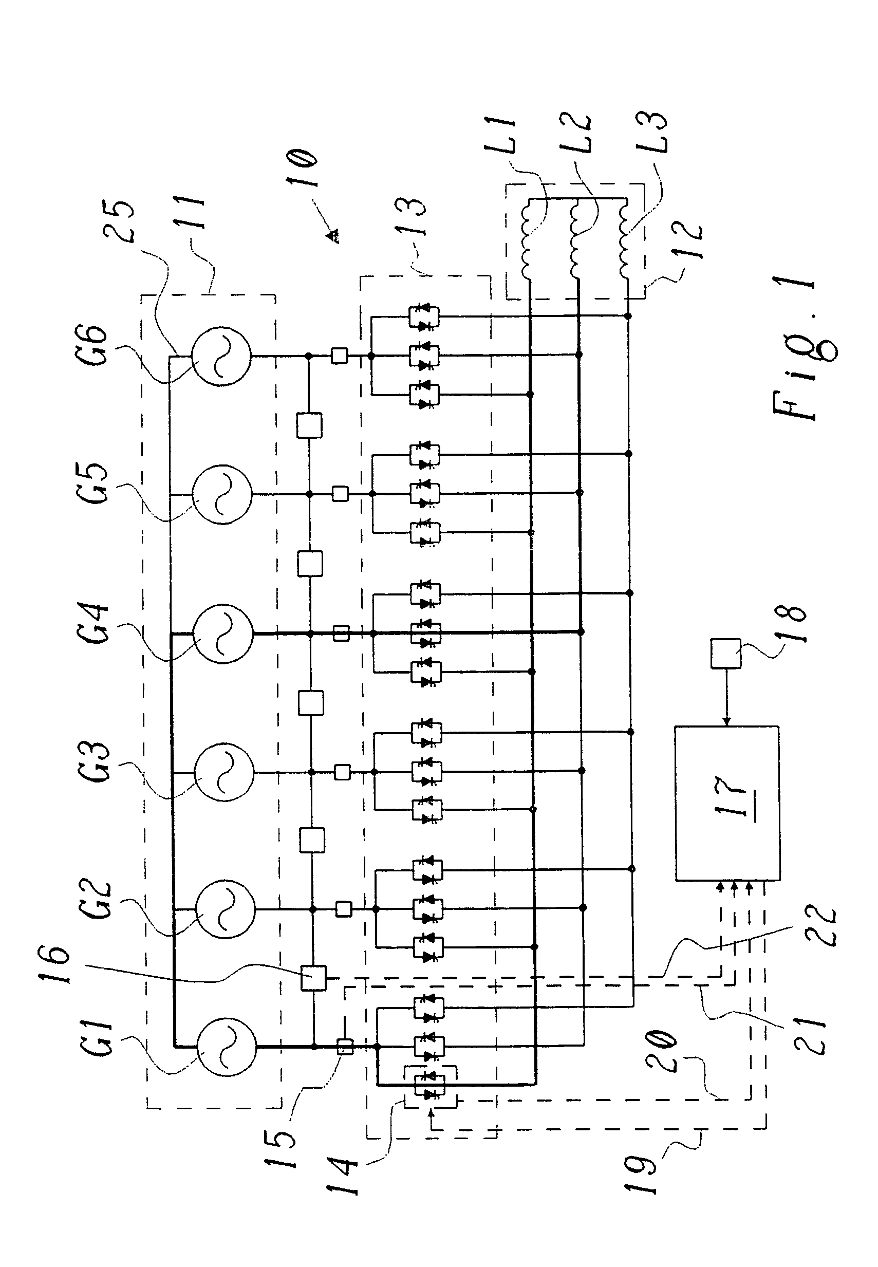
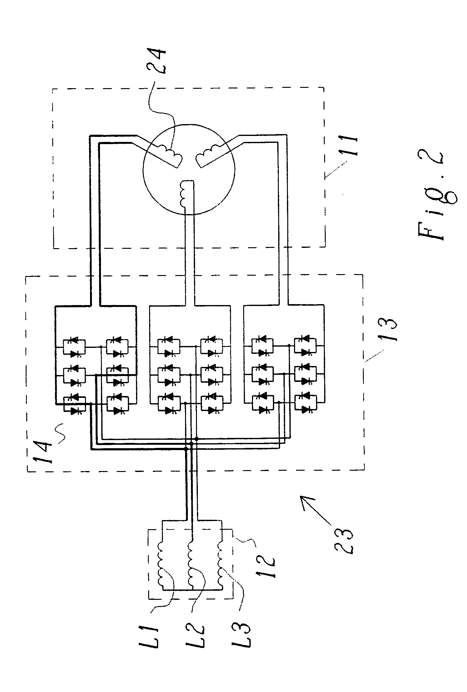
[0050]FIG. 1 shows a schematic circuit diagram of a matrix converter comprising 6 input phases and 3 output phases which is designed and controlled to allow natural commutations only. Such a matrix converter has been disclosed in DE 10051222 A1 as well as in the corresponding EP 1199794 A2. The proposed principle can however also be applied to matrix converters which use forced commutation. A matrix converter as described in these documents as well as its mode of operation as described therein shall form the basis for the examples given here. The matrix converter 10, when being used to convert the frequency of the voltage generated by the generator 11 to a frequency as requested by the load 12, i.e. the grid to which the generator is connected, in a time sequence 6 connects phases G1, . . . ,G6 of a generator 11 to the 3 phases L1, . . . ,L3 of a load 12. The power component 13 required for it comprises 18 bi-directional switches 14 in the form of antiparallel switched thyristors. T...


PUM


Abstract

A method for operating a matrix converter that includes converting m phases of a generator into alternating voltage with n phases of a load connected to a network, wherein n<m. The n phases of the load are alternatingly connected via a multiple number of controllable bi-directional switches arranged in an (m×n) matrix, whereby n phases of the generator are always connected with the load while (m−n) phases of the generator are not connected with the load. The matrix converter may be used for at least part of the start-up process, in particular for the initial part of the start-up process of the generator reversely operating the matrix converter in cycloconverter mode using power available from the network, wherein the group of m phases of the generator are grouped in corresponding subgroups.

Description

[0001] This patent application is a continuation of International Patent Application No. PCT / EP2003 / 050808, filed on Nov. 10, 2003, which claims priority to German Patent Application No. DE 102 52 234.0, filed on Nov. 11, 2002. The entire disclosure of both applications is incorporated by reference herein.[0002] The present invention relates to the field of power electronics and in particular to power generation with a synchronous generator which is operated above the synchronous mains frequency, as well as the drive of variable-speed synchronous motors and induction motors. Particularly, the present invention relates to a method for operating a matrix converter which when being operated to convert m phases of a generator into alternating voltage with n (n<m) phases of a load connected to a network alternatingly connects the n phases of the load via a multiple number of controllable bi-directional switches arranged in an (m×n) matrix, whereby n phases of the generator are always ...

Claims


Application Information

Patent Timeline
Patent Type & Authority Applications(United States)
IPC IPC(8): H02M5/27
CPCH02M5/271
Inventor LACAZE, ALAINTURRI, SYLVIE
Owner GENERAL ELECTRIC TECH GMBH
Why Eureka
Try Eureka