[0009] So that the manner in which the above recited features, advantages and objects of the present invention are attained can be understood in detail, a more particular description of the invention briefly summarized above, may be had by reference to the embodiments thereof which are illustrated in the appended drawings. It is noted, however, that the appended drawings illustrate only typical embodiments of this invention and are therefore not to be considered limiting of its scope, for the invention may admit to other equally effective embodiments.
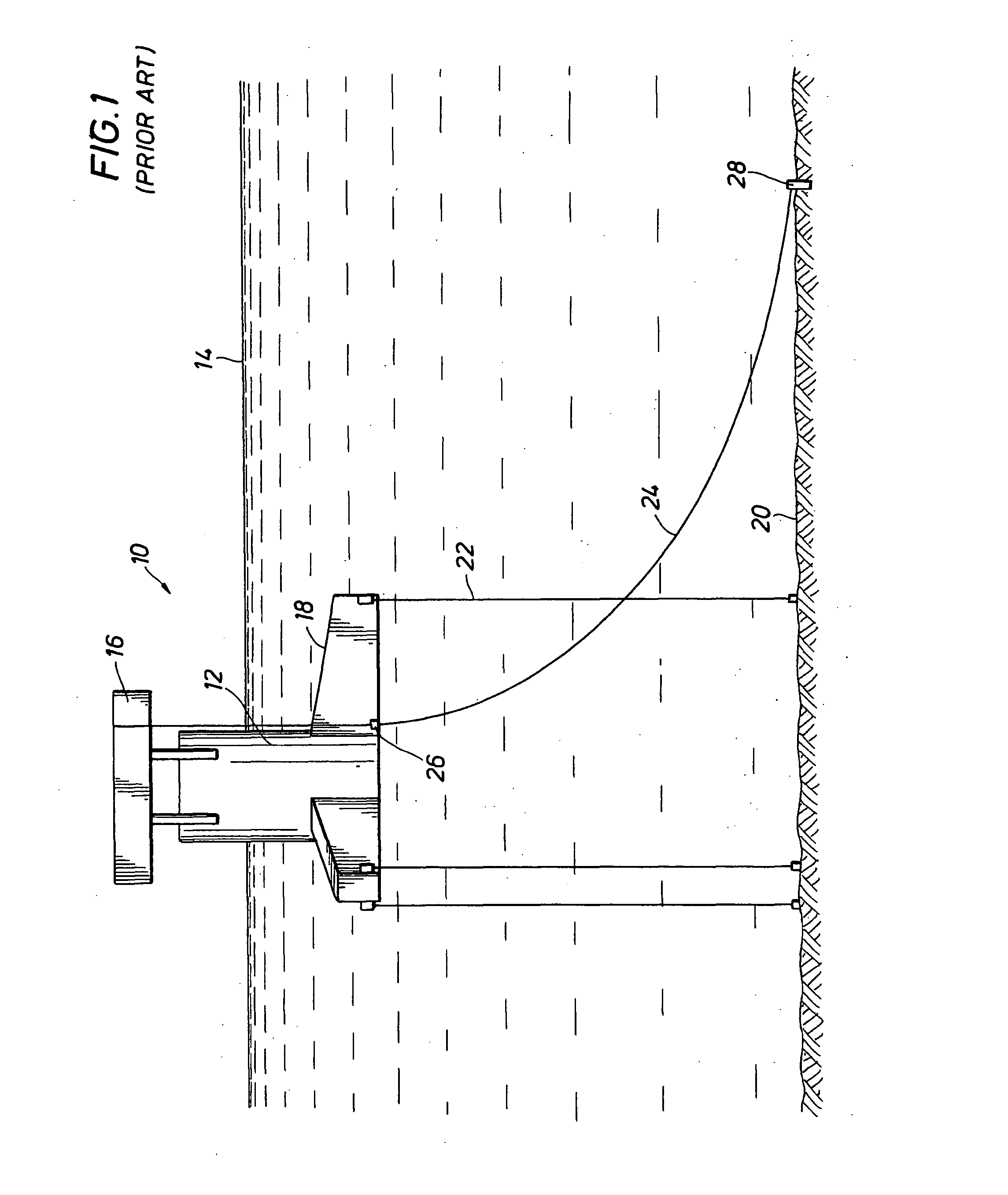
[0010]FIG. 1 is a side view of a prior art steel
catenary riser supported on a TLP illustrating the riser catenary path to the touchdown point on the seabottom;
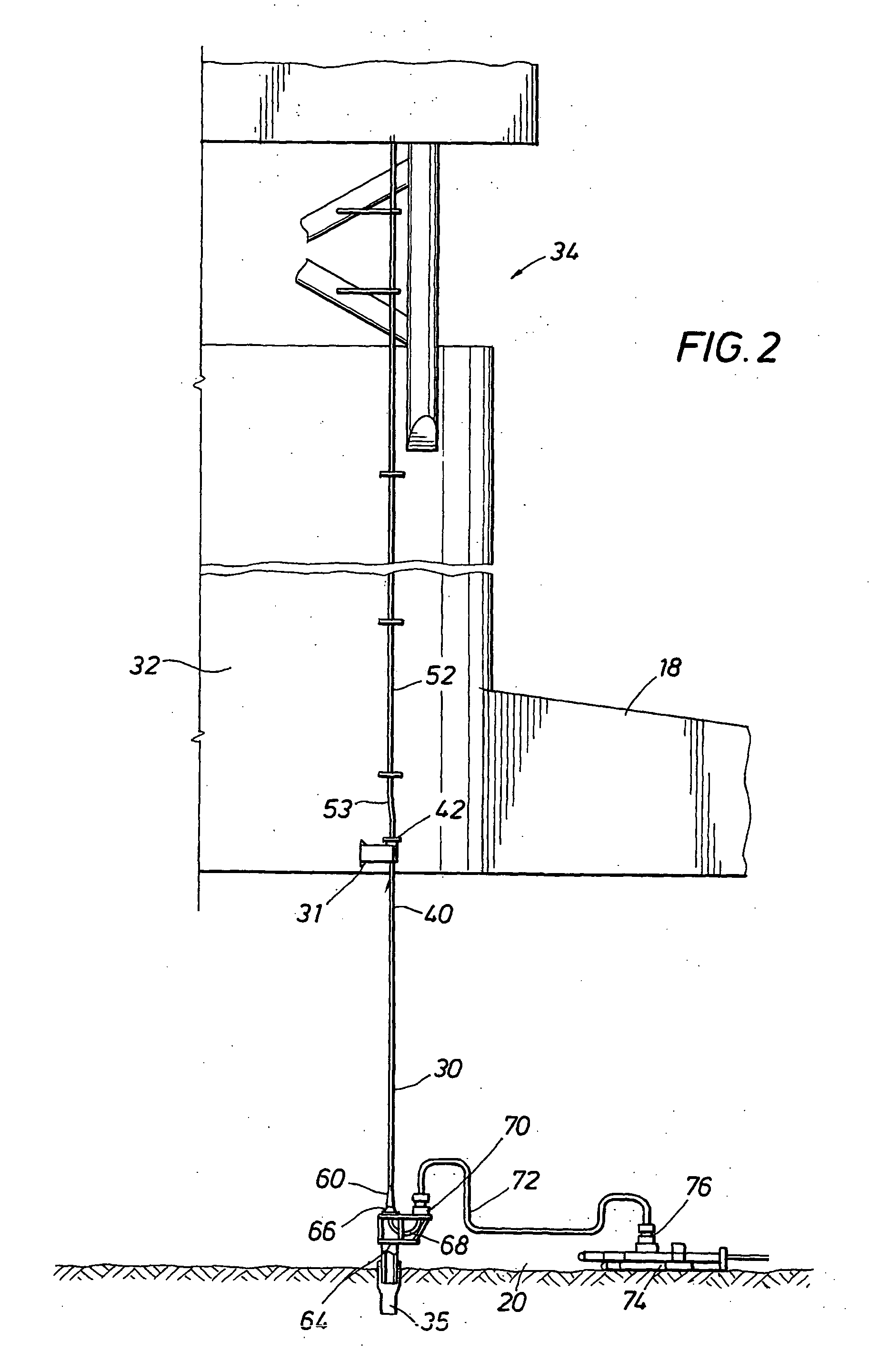
[0011]FIG. 2 is a partially broken away side view of a TLP depicting the top tensioned riser of the present invention secured near the
keel of a platform
hull;
[0012]FIG. 3 is a partially broken away side view of the upper connector
assembly of the top tensioned riser of the present invention secured near the
keel of a platform
hull;
[0013]FIG. 4 is a top plan view of the upper connector
assembly of the top tensioned riser of the present invention taken along line 4-4 of FIG. 3; and
[0014]FIG. 5 is a side view illustrating the bottom
assembly of the top tensioned riser of the present invention connected to a
pile anchored to the seabottom;
[0015] Referring first to FIG. 1, a typical mono-column TLP platform, generally identified by the reference numeral 10, is shown. The platform 10 includes a column or hull 12 projecting above the water surface 14 supporting one or more platform decks 16 thereon. Pontoons 18 extend radially outward from the bottom of the hull 12. The platform 10 is anchored to the seabottom 20 by tendons 22. A steel catenary riser 24 is supported at a
porch 26 near the keel level of the platform hull 12. The catenary riser 24 takes a catenary path to the touchdown point 28 on the seabottom 20. The riser 24 may be hundreds or thousands of feet in length and is freely suspended between the support porch 26 and the touchdown point 28. Ocean currents could therefore move the riser 24 so that it interferes with the tendons 22 under certain environmental conditions.
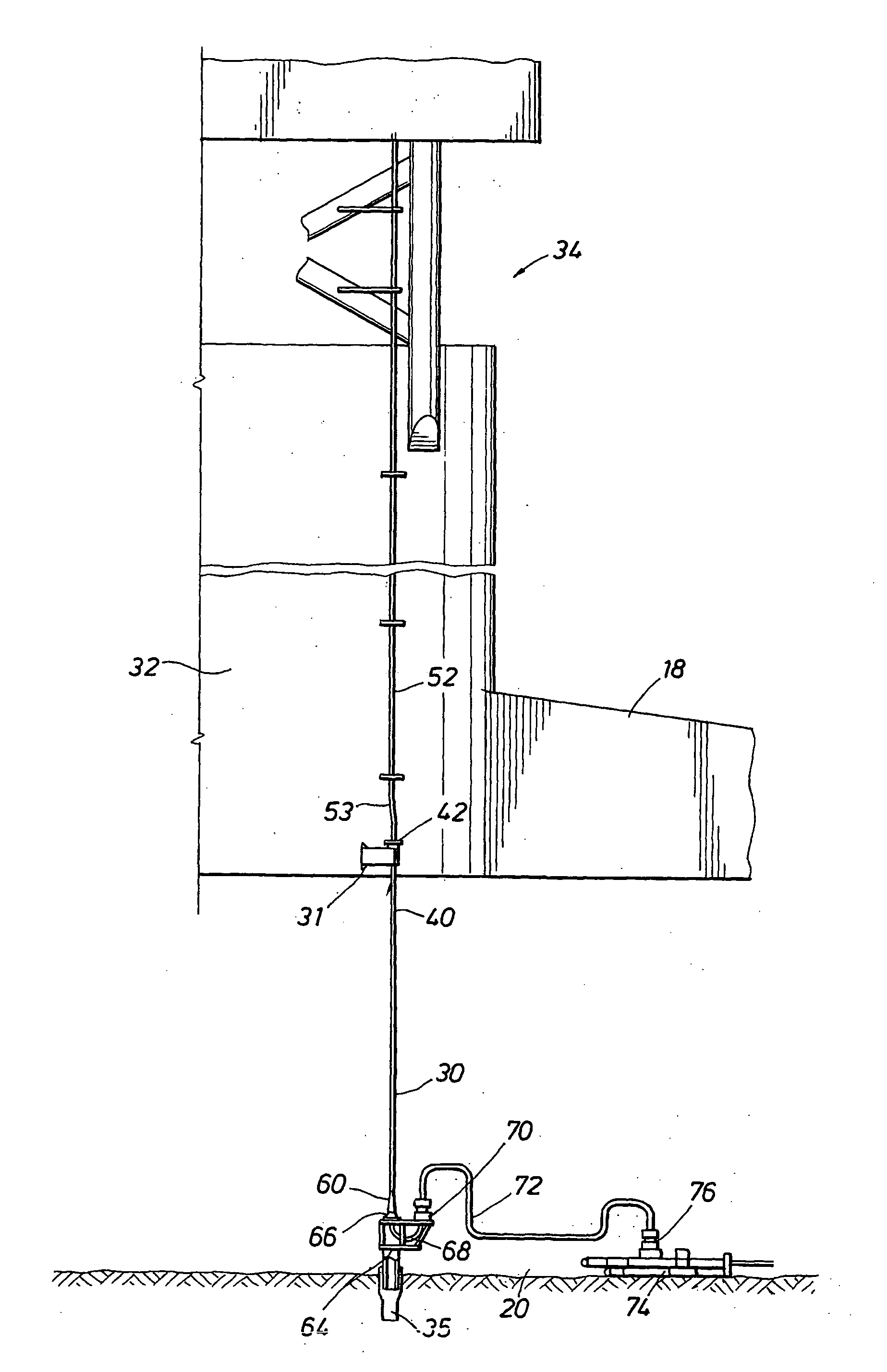
[0016] Referring now to FIG. 2, the top tensioned riser 30 of the present invention extends substantially vertically downward from a riser porch 31 located external to the hull 32 of a TLP platform 34 to an anchor
pile 35 secured in the seabottom 20. The upper end of the riser 30 is supported by the riser porch 31 near the keel of the platform hull 32. The riser 30 is tensioned at installation to control stresses. However, the riser 30 is not maintained in constant tension as a conventional tensioned riser would be, rather its loads are allowed to fluctuate through a pre-calculated and permissible range. The riser 30 behaves similar to a
tendon in this respect, but the tension in the riser 30 is much lower because it does not materially participate in the stationkeeping of the platform 34. The riser 30 is like a limp
tendon that is installed at a location that reduces the dynamic forces exerted by the platform 34 on the riser 30.
[0017] In a preferred embodiment of the present invention, the riser 30 is installed similar to a preinstalled
tendon 22. That is, the riser 30 is stalked together in vertical sections and terminated at the top end thereof with temporary
buoyancy (not shown in the drawings) that supports the riser 30 in a substantially vertical position until the hull 32 is installed. Standard riser joints utilizing premium threaded and coupled connections connected end-to-end form the riser 30. Fairings are used to suppress vortex induced vibration (VIV). When the hull 32 is de-ballasted to establish pre-tension in the tendons 22, the riser 30 is also pretensioned, but to a lesser load. The riser 30 connects an import / export flowline to the TLP facilities.
[0018] The main riser joints forming the riser 30 of the present invention are similar to standard tubing with threaded and coupled connections. The bottom assembly of the riser 30 includes an open frame structure for securing the lower end of the riser 30 to the anchor pile 35. The upper end of the riser 30 terminates in an upper tapered stress joint 40 and length adjustment joint 42, shown in FIG. 3. The upper end of the riser 30 is locked off to the hull 32 and then pre-tensioned during de-ballasting of the hull 32 to a predetermined top tension.
[0019] Referring now to FIG. 3, the length adjustment joint 42 is welded or otherwise secured to the upper tapered stress joint 40 of the riser 30. The length adjustment joint 42 is externally threaded or grooved and extends through the riser porch 31. A riser lock off connector assembly 44 mounted on the length adjustment joint 42 permits adjustment of the length and tension of the riser 30. The lock off assembly 44 comprises a top termination riser connector 45, a segmented slip 46 and a plate 47 having a centrally located hole 49. The length adjustment joint 42 extends through the hole 49 of the plate 47 which is positioned in facing contact with load cells 48 embedded in the surface of the riser porch 31. The termination riser connector 45 and segmented slip 46 threaded on the length adjustment joint 42 engage the back side of the plate 46 to maintain it in contact with the load cells 48 and to lock the riser 30 to the riser porch 31. The tension in the riser 30 is monitored via the load cells 48 which are operatively connected to sensors relaying data to a monitor or the like located on the
deck of the TLP platform. No external tensioning
system is required. The upper end of the length adjustment joint 42 is connected to the hull
piping 52 by a
jumper joint53, shown in FIG. 2.
[0020] Referring now to FIG. 5, the lower end of the riser 30 terminates in a tapered stress joint 60. An open frame support structure 64 is mounted on the lower distal end of the riser stress joint 60. A mandrel 65 extending downwardly from the bottom of the open frame support structure 64 anchors the riser 30 to the pile 35 installed in the seabottom 20 in a known manner. The mandrel 65 stabs into the upper end of the pile 35 projecting above the seabottom 20 and establishes a secure connection therewith. The open frame support structure 64 is provided with connectors required for establishing fluid communication between the riser 30 and import / export flowlines.
[0021] The tapered stress joint 60 of the riser 30 connects to an anchor
flange 66 securing one end of a flowline loop 68 to the open frame support frame structure 64. The opposite end of the flowline loop 68 connects to a flowline connector hub 70 mounted on the support structure 64. A flowline
jumper 72 connects a PLET 74 to the flowline connector hub 70. The PLET 74 includes a flowline connection hub 76 for establishing fluid communication with one or more import / export flowlines and / or pipelines. The PLET 74 incorporates isolation valves 78 to prevent flowline flooding and allow testing after the flowline
jumper installation. The flowlines 68, 72 include 5D minimum
radius bends to allow for
pigging and other maintenance operations.
[0022] Riser installation, which may include one or more risers 30, may be done before or after installation of the TLP. For riser installation prior to installation of the TLP, the anchor pile 35 is first installed in the seabottom 20 in a known manner. The anchor pile 35 is sized for the expected load conditions and may be, for example, 36 inches in
diameter and approximately 200 feet long made up with standard connectors. The lower riser stress joint 60 with the open frame support structure 64 mounted on the lower distal end thereof is the first joint forming the riser 30. Subsequent riser joints are connected end-to-end and run down until the riser 30 is formed. Upon completion of the riser 30, temporary
buoyancy is provided at the upper end of the riser 30 to maintain it in a vertical position until the hull 32 is installed. The riser 30 is pressure tested and the lower end thereof is then locked in the anchor pile 31. Upon lowering of the hull 32 to the installation draft, the length adjustment joint 42 of the riser 30 is guided through the riser porch 31. The length of the riser 30 is adjusted as necessary. The length adjustment joint 42 provides about 4 feet of a threaded or grooved profile section for fine adjustments of the length of the riser 30. The riser 30 length is adjusted as necessary and the riser 30 is pre-tensioned to the installation tension and locked off to the hull 32. The temporary
buoyancy is removed and the hull
piping 52 is then connected to the length adjustment joint 42. The PLET installation may be installed before or after the riser 30 is installed. If the PLET is already in place, the flowline connections are made to establish fluid flow communication with the import / export flowlines and / or pipelines.
[0023] If the riser 30 is installed after installation of the TLP, a similar installation sequence is followed. After the TLP is installed, a crane mounted on the TLP
deck or a heavy lift vessel moored adjacent to the TLP is used to install the riser 30. As in the installation sequence described above, the lower riser stress joint 60 with the open frame support structure 64 mounted on the lower distal end thereof is the first joint forming the riser 30. Subsequent riser joints are connected end-to-end and run down until the riser 30 is formed. The crane or heavy lift vessel tensions and holds the riser 30 while it is guided into the riser porch 31. The length of the riser 30 is adjusted as necessary and the riser 30 is pre-tensioned to the installation tension and locked off to the hull 32. The hull
piping 52 is then connected to the length adjustment joint 42. The PLET 74 is installed, if it is not already in place, and the flowline connections are made to establish fluid flow communication with the import / export flowlines and / or pipelines.
[0024] While preferred embodiments of the invention has been shown and described, other and further embodiments of the invention may be devised, such as utilizing the top tensioned riser of the invention with a multi-column TLP, without departing from the basic scope thereof, and the scope thereof is determined by the claims that follow.

