Bookbinding apparatus

a book binding and book stack technology, applied in the field of compact and simple book binding apparatus, can solve the problems of degrading the finish of the book, the thickness of the sheet stack to be bound does not always fit the spine width of the cover, and the type of book binding apparatus cannot be used for pad binding, so as to achieve the effect of easy removal of excessive adhesiv

Inactive Publication Date: 2005-10-27
DUPLO SEIKO CORP
View PDF12 Cites 25 Cited by
  • Summary
  • Abstract
  • Description
  • Claims
  • Application Information

AI Technical Summary

Benefits of technology

[0046] Referring to the bookbinding apparatus according to the present invention, a large amount of adhesive is prone to stick to an end portion of the sheet stack, because the adhesive on the roller surface is scraped off by a lateral edge at both ends of the sheet stack. Especially in case of case binding with a cover, an excessive amount of adhesive stuck to end portion of the sheet stack produces a protrusion of solidified adhesive, resulting in a defective finish of the book. Therefore, it is desirable to prevent deposition of a large amount of adhesive at both edges of the sheet stack.
[0047] For this purpose, the adhesive tank is moved with the roller stopped, in the proximity of a final edge of the sheet stack. By such arrangement, the adhesive is no longer supplied from the adhesive tank, and the adhesive remaining on the roller surface is spread over in a region close to the edge of the sheet stack. Consequently, deposition of an excessive amount of adhesive in the proximity of a final edge of the sheet stack can be prevented.
[0048] Also, a reason that the roller is stopped only in a backward travel in the foregoing constitution is that surplus adhesive stuck to the end portion in a forward travel can be removed by the roller on its way back, while surplus adhesive on the end portion in the backward travel (the final end) cannot be thus removed by the roller. Accordingly, the above constitution permits easily removing the excessive adhesive by changing an applying condition via the roller.
[0049] Consequently, according to the bookbinding apparatus of the eighteenth aspect, by moving the adhesive tank with the roller stopped in the proximity of an edge of the sheet stack, where an excessive amount adhesive is prone to stick, the adhesive is no longer supplied from the adhesive tank, and the adhesive remaining on the roller surface is applied so as to be spread over. Consequently, deposition of an excessive amount of adhesive in the proximity of a final edge of the sheet stack can be prevented.

Problems solved by technology

However, since a specifically designed cover having a predetermined spine width is used in this type of bookbinding apparatus, a thickness of the sheet stack to be bound does not always fit the spine width of the cover.
In such a case a gap is produced between the cover and an uppermost page of the sheet stack, thereby degrading the finish of the book.
Besides, this type of bookbinding apparatus cannot be used for pad binding, which is a method of binding a paper pad coated with an adhesive without enclosing in a cover.
However, in this bookbinding apparatus, since the sheet stack moves back and forth over the roller together with the paper holder, in a longitudinal direction along the back of the sheet stack, the apparatus has to be at least wider than a double of the length of the sheet stack; therefore it is difficult to make the apparatus smaller in size.
However, these types of bookbinding apparatus are generally provided with an adhesive tank having a large capacity, to replenish the adhesive less frequently.
Especially in case of a bookbinding apparatus that moves a sheet stack in a widthwise direction, since the roller has to be sufficiently long, the adhesive tank for retaining the adhesive to be applied to the sheet stack with the roller naturally has to be long, and hence has a large capacity.
Besides, a larger amount of adhesive volatilizes from the adhesive tank, resulting in increase of smell of resin or rubber contained in the adhesive melted by a high temperature.

Method used


Image

  • Bookbinding apparatus
  • Bookbinding apparatus
  • Bookbinding apparatus

Examples


Embodiment Construction

[0078] Before the description of the present invention proceeds, it is to be noted that like parts are designated by like reference numerals throughout the accompanying drawings.

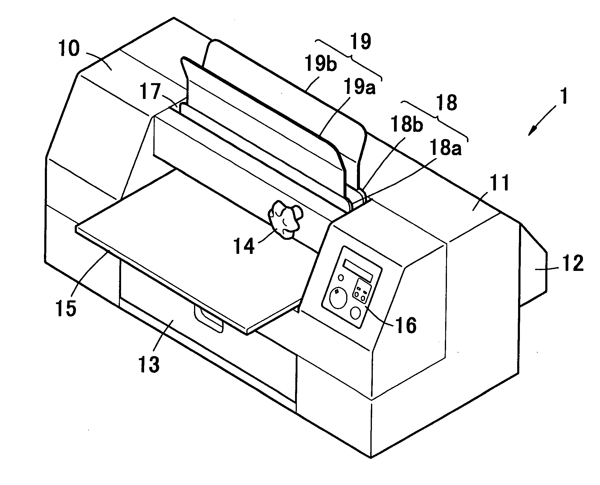
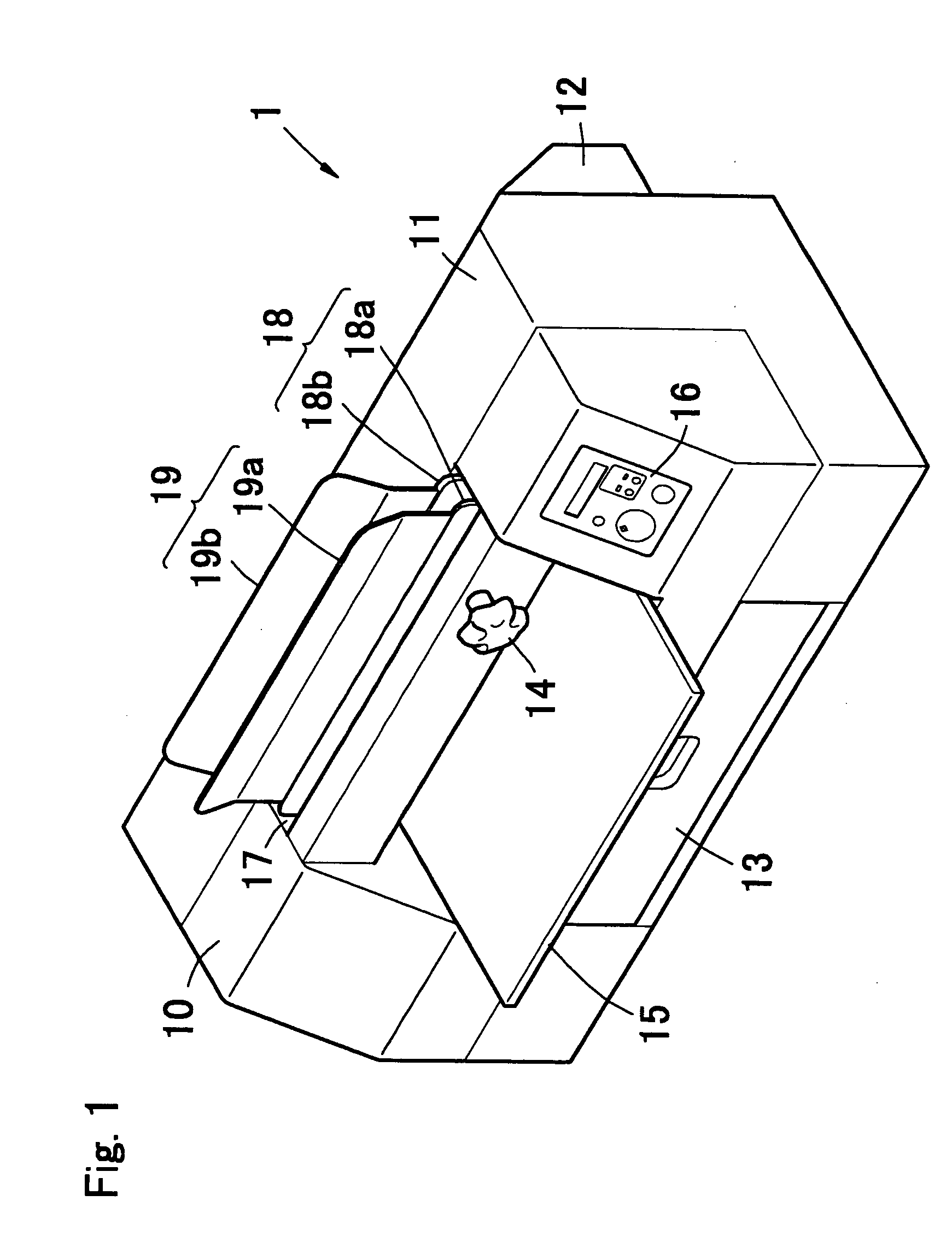
[0079]FIG. 1 is a perspective view showing an outer appearance of a bookbinding apparatus according to an embodiment of the present invention. The bookbinding apparatus 1 is a generally box-shaped apparatus, provided with a casing including a front housing 10 constituting a front and an upper face of a main body, and a rear housing 11 constituting a rear and an upper face thereof. The front housing 10 and the rear housing 11 are fixed to a frame 28, 29, 41a and 41b (Ref. FIG. 7) provided inside the main body, as will be described later. The rear housing 11 is provided with a rear cover 12 on a rear face thereof, which has an inclined wall for securing an additional space for a cover for bookbinding (110x of FIG. 20A) and a movable plate 46, and for bending the cover 110x downward to retain temporarily (Ref....


PUM


Abstract

In a bookbinding apparatus (1) comprising an adhesive tank (23) for retaining therein an adhesive melted by heat, a roller (24) ratatably supported with the adhesive tank so as to dip a lower portion thereof in the adhesive retained in the adhesive tank, for applying the adhesive to a sheet stack along a lateral edge thereof, and a holding unit (18) capable of holding the sheet stack, an adhesive tank carrier (76, 78), the movably constituted adhesive tank (23) and the roller (24) are disposed at a stand-by position located outside a longitudinal end face of the sheet stack held by the holding unit (18) in a stand-by stage so that the adhesive tank is contactlessly heated to melt the adhesive, and are moved together from the stand-by position in a longitudinal direction of the sheet stack substantially through an entire area under a back face thereof in a bookbinding stage.

Description

TECHNICAL FIELD [0001] The present invention relates to a compact and simple bookbinding apparatus to be used in an office, school, home, etc., which applies a hot-melt adhesive in a melted state to a lateral face of a sheet stack corresponding to a back of a book. BACKGROUND ART [0002] Up until now, small bookbinding apparatuses for binding a book in a simple manner by applying an adhesive to a sheet stack have been popularly used in an office, school, home, etc. Most of such bookbinding apparatuses require a cover specifically designed for the apparatus, provided with a hot-melt adhesive applied in advance to an inner face of its spine. A sheet stack enclosed in such cover is set in the bookbinding apparatus, and a heater of the apparatus melts the adhesive provided inside the cover, thereby bonding the sheet stack and the cover together. [0003] However, since a specifically designed cover having a predetermined spine width is used in this type of bookbinding apparatus, a thicknes...

Claims


Application Information

Patent Timeline
Patent Type & Authority Applications(United States)
IPC IPC(8): B05C1/02B42C9/00B05C9/14B05C13/02B42C11/06
CPCB42C9/0012
Inventor OOTA, RYUICHI
Owner DUPLO SEIKO CORP
Why Eureka
Try Eureka