Array-antenna-equipped communication apparatus and method of calibrating array-antenna-equipped communication apparatus

a communication apparatus and array technology, applied in the direction of receiving monitoring, electromagnetic wave modulation, polarisation/directional diversity, etc., can solve the problems of cumbersome and time-consuming procedure, stop the calibration process and disable the appropriate calibration,

Inactive Publication Date: 2005-10-27
FUJITSU LTD
View PDF8 Cites 59 Cited by
  • Summary
  • Abstract
  • Description
  • Claims
  • Application Information

AI Technical Summary

Benefits of technology

[0013] A communication device according to an aspect of the present invention includes an array of antennas and a plurality of antenna branches, each of the antenna branches including a transmitting unit for transmitting a signal. The communication device fu

Problems solved by technology

However, the conventional technology cannot ensure the convergence of the adaptive control algorithm employed in the calibration, thereby causing the calibration process to stop and disabling appropr

Method used


Image

  • Array-antenna-equipped communication apparatus and method of calibrating array-antenna-equipped communication apparatus
  • Array-antenna-equipped communication apparatus and method of calibrating array-antenna-equipped communication apparatus
  • Array-antenna-equipped communication apparatus and method of calibrating array-antenna-equipped communication apparatus

Examples


first embodiment

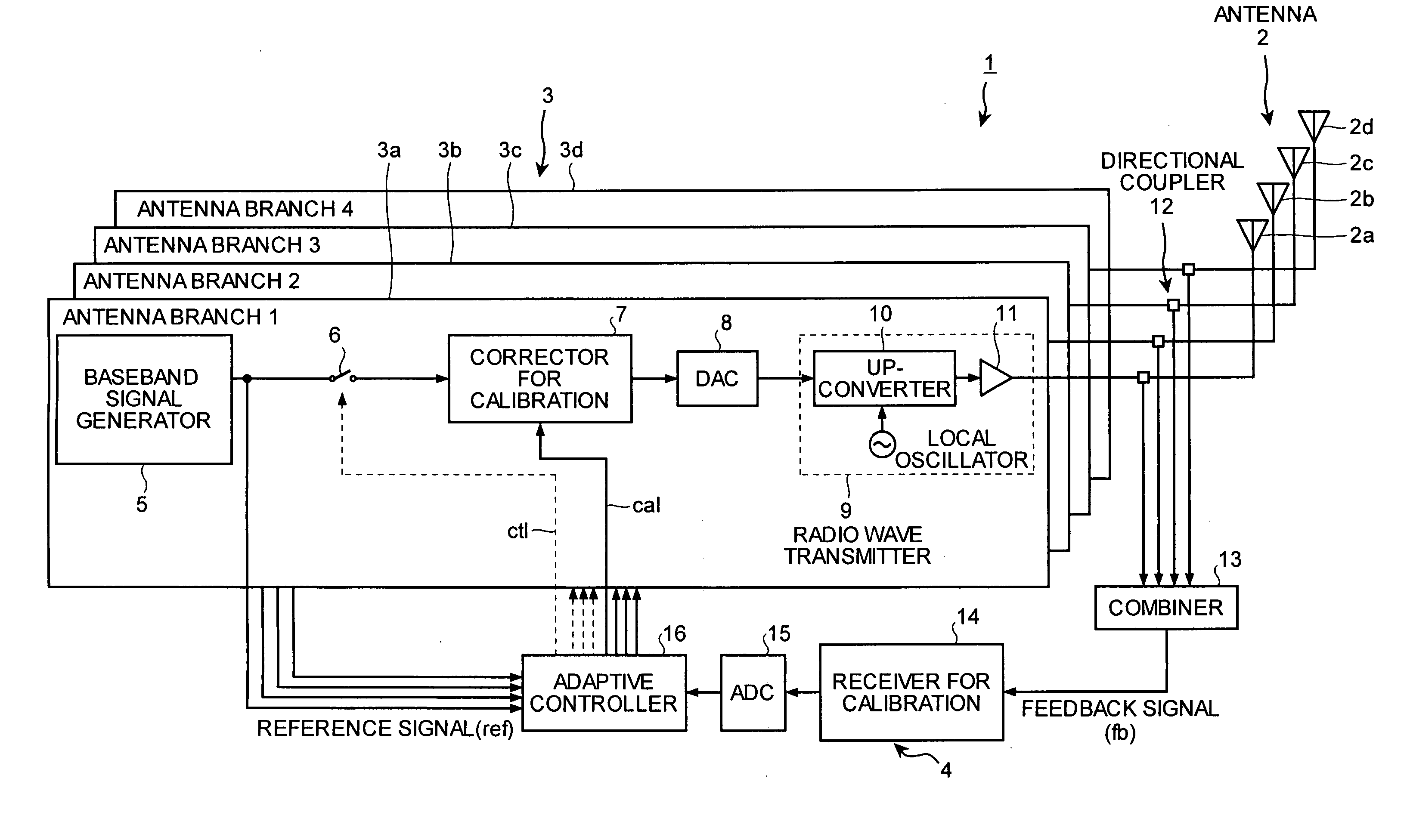
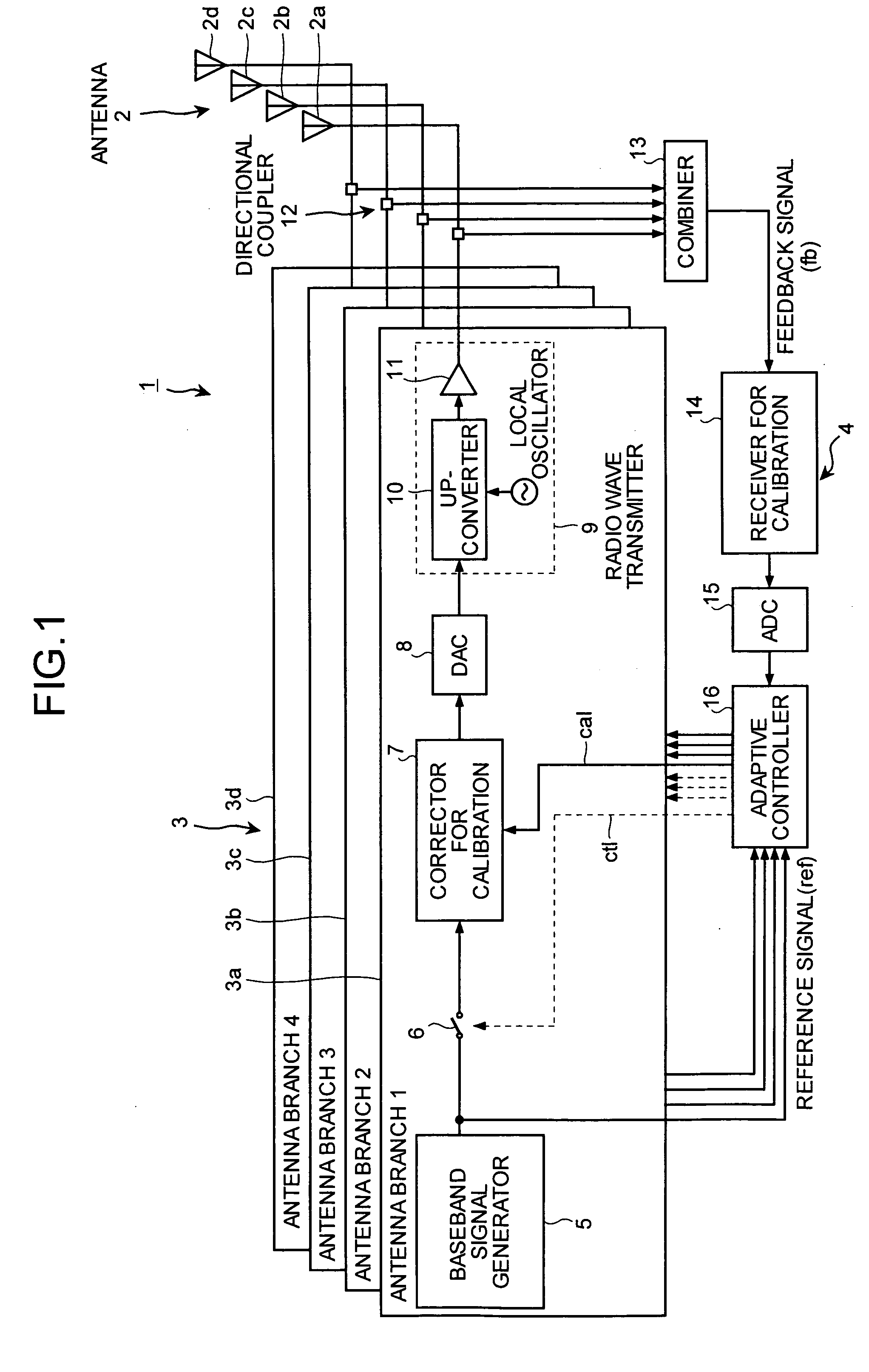
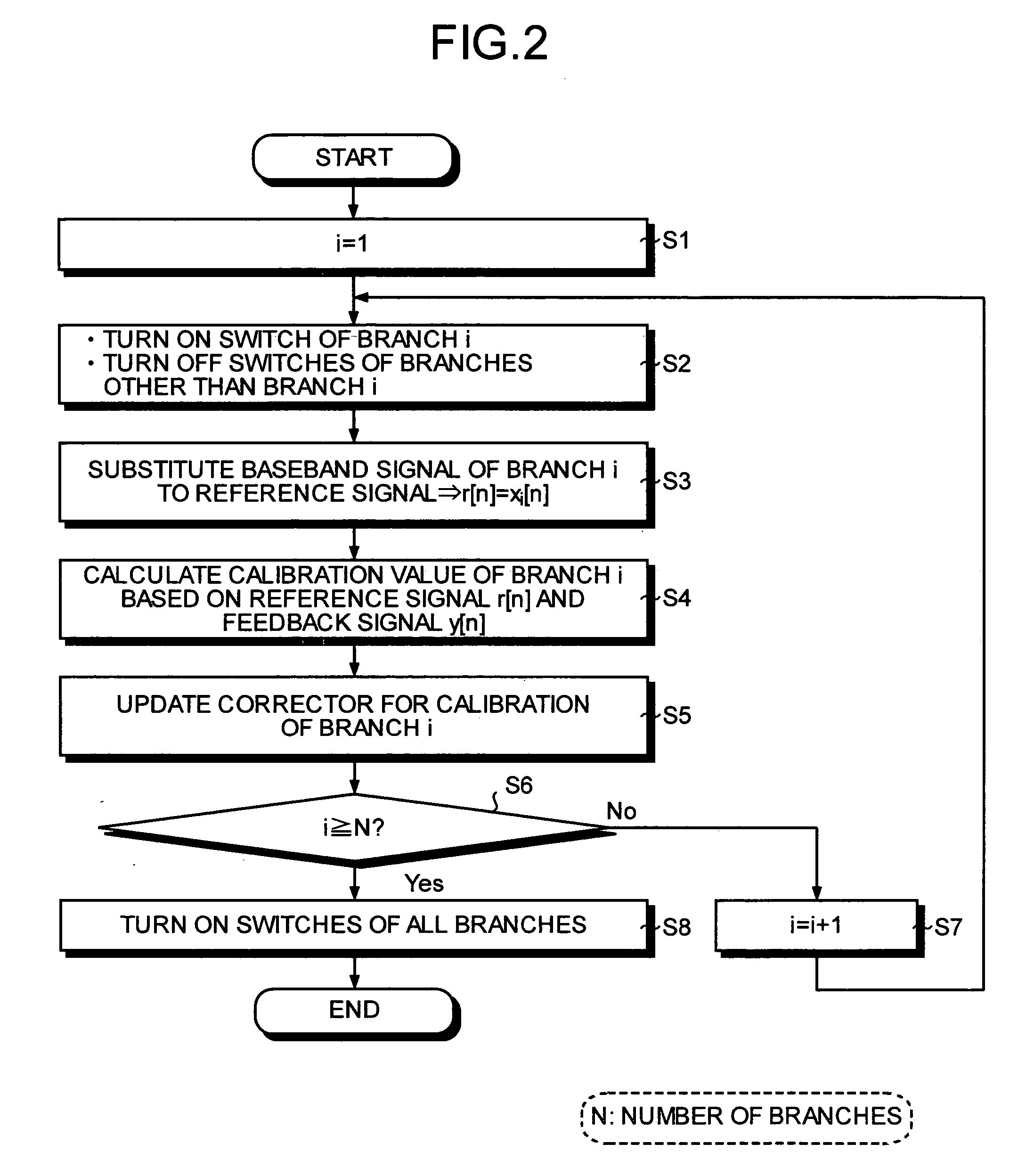
[0037]FIG. 2 is a flowchart of a calibration process performed by the adaptive controller 16 according to the An initial value 1 of the branch i to be calibrated is set (step S1). The switch 6 of the branch i is turned on, and the switches 6 of branches other than the branch i are turned off (step S2). The baseband signal of the branch i is substituted to the reference signal ref (r[n]=xi[n]) (step S3).

[0038] Based on the reference signal ref (r[n]) and the feedback signal fb (y[n]), the calibration value cal of the branch i is calculated (step S4), based on which the corrector for calibration 7 of the branch i is updated (step S5). When i=1, the calibration value cal stored in the corrector for calibration 7 of the antenna branch 3a is updated.

[0039] A method of initial calibration on the branch i at step S4 is described. When the baseband signal is of a narrow band, the amplitude / phase deviation of the radio wave transmitter 9 at each of the antenna branches 3 can be represented...

second embodiment

[0046]FIG. 3 is a flowchart of a calibration process performed by the adaptive controller 16 according to the An initial value 1 of the branch i to be calibrated is set (step S11). The switches 6 of the branches 1 to i are turned on, and the switches 6 of the other branches i+1 to N are turned off (step S12). The baseband signal of the branch i is substituted to the reference signal ref (r[n]=xi[n]) (step S13). As for the feedback signal, y[n]−(xi[n]w1*[n]+ . . . +xi-1[n]wi-1*[n]) is substituted to the feedback signal fb (y[n]=y[n]−(xi[n]w1*[n]+ . . . +xi-1[n]wi-1*[n])) (step S14).

[0047] Based on the reference signal ref (r[n]) and the feedback signal fb (y[n]), a calibration value cal of the branch i is calculated (step S15), based on which the corrector for calibration 7 of the branch i is updated (step S16). Thereafter, it is determined whether calibration has been completed for all N branches (step S17). If calibration has not been completed (“No” at step S17), the branch i to ...

third embodiment

[0051]FIG. 5 is a flowchart of a calibration process performed by the adaptive controller 16 according to the An initial value 1 of the branch i to be calibrated is set (step S21). The switch 23 of the branch i is switched to the port A, and the switches 23 of the branches other than the branch i are switched to the port B (step S22). The initial value 1 of the number of times k for phase shifting is set (step S23). The phase of the baseband signal of the branch i is shifted by the phase shifter 22 based on the following Eq. (5), where Δφ is a predetermined step size of shifting of the phase shifter 22 (step S24).

φ=(k−1)·Δφ  (5)

[0052] The baseband signal of the branch i (r[n]=xi[n]) is selected as the reference signal ref (step S25) and, based on the current feedback signal fb (y[n]), the calibration value of the branch i is calculated (step S26). Then the power of an error signal e[n] representing a difference between the reference signal ref and feedback signal fb is calculated ...


PUM


Abstract

In an array-antenna-equipped communication apparatus, a part of a transmission signal after passing through a radio wave transmitter is branched by a directional coupler, combined by a combiner, converted to a baseband signal by a receiver for calibration, analog-converted by an analog-to-digital converter, and input to an adaptive controller as a feedback signal. The adaptive controller calculates a calibration value that minimizes the power of an error signal representing a difference between the feedback signal and a reference signal, which is the transmission signal before passing through the radio wave transmitter, and outputs the calibration value to a corrector for calibration.

Description

BACKGROUND OF THE INVENTION [0001] 1) Field of the Invention [0002] The present invention relates to an array-antenna-equipped communication apparatus with a function of calibrating a deviation of amplitude / phase of a plurality of antenna branches. [0003] 2) Description of the Related Art [0004] An array-antenna-equipped communication apparatus includes an array of antennas and antenna branches provided for the respective antennas. The array-antenna-equipped communication apparatus can control directivity of the antennas by transmitting a signal with its phase and amplitude being adjusted (weighted) for each antenna branch. The difference in amplitude / phase is required to be the same, even at antenna ends, among the antenna branches. Therefore, to optimally operate the array-antenna-equipped communication apparatus, a calibration process is required for solving an amplitude / phase deviation among antenna branches due to a power amplifier (PA) and a mixer included in a radio wave tran...

Claims


Application Information

Patent Timeline
IPC IPC(8): H01Q21/00H04B7/10
CPCH04B17/12H04B17/21H04B17/19H04B17/18
Inventor FUDABA, NOBUKAZUKUBO, TOKURONAGATANI, KAZUOISHIKAWA, HIROYOSHI
Owner FUJITSU LTD
Why Eureka
Try Eureka