Machine tool with a work spindle

a technology of work spindle and machine tool, which is applied in the direction of metal-working holders, supporters, positioning apparatuses, etc., can solve the problems of considerable more expensive manufacturing and maintenance of two-spindle machine tools than of one-spindle machines, and achieves the effect of reducing manufacturing costs, facilitating handling, and optimizing the available circumferen

Inactive Publication Date: 2005-10-27
GROB WERKE BURKHART GROB E K
View PDF0 Cites 11 Cited by
  • Summary
  • Abstract
  • Description
  • Claims
  • Application Information

AI Technical Summary

Benefits of technology

[0010] The problem according to the invention is solved, as described above, by a machine tool which has only one work spindle which carries and drives a machining tool which can be exchanged, as well has a tool supply which has tool tongs for receiving machining tools. Even with such an alternative machine tool a relative movement between tool magazine and work spindle is provided for exchanging, respectively replacing, machining tools at the work spindle. In order to solve the problem according to the invention it is suggested here that the to

Problems solved by technology

These two-spindles machine tools, however, are considerable more e

Method used


Image

  • Machine tool with a work spindle
  • Machine tool with a work spindle
  • Machine tool with a work spindle

Examples


Embodiment Construction

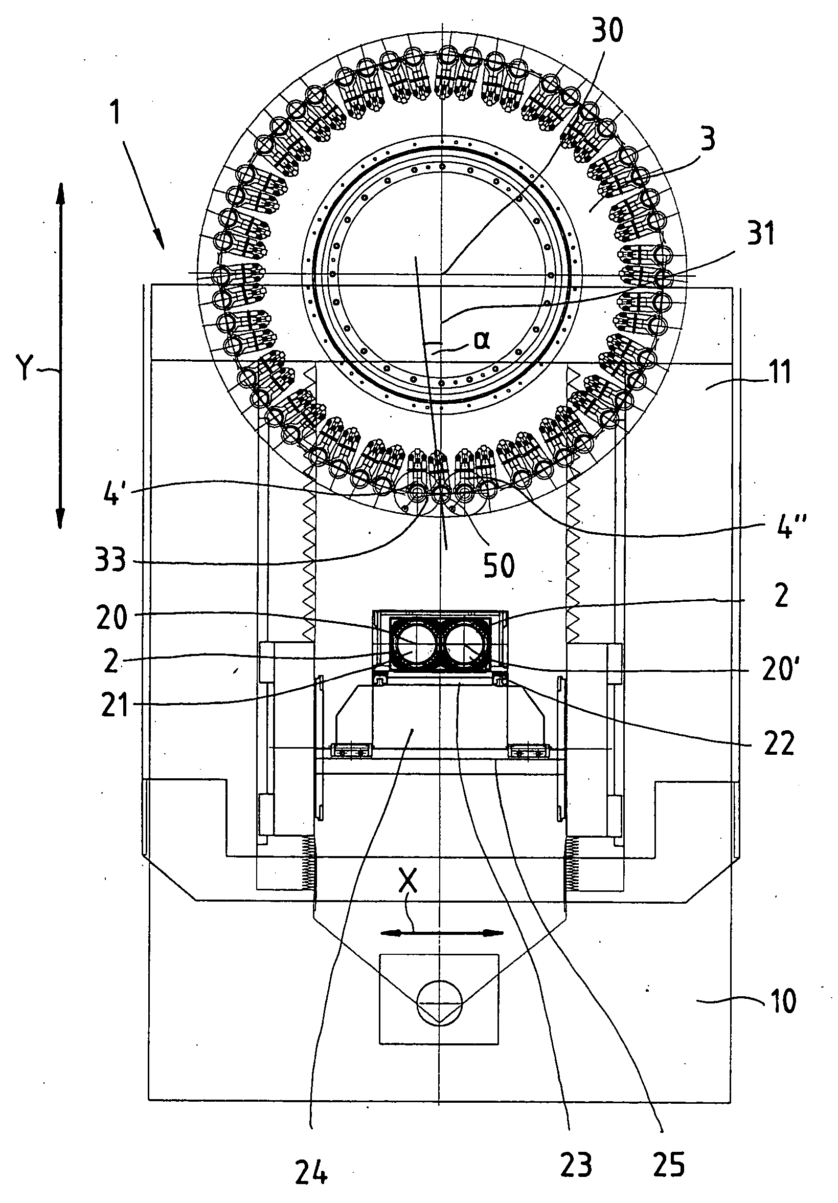
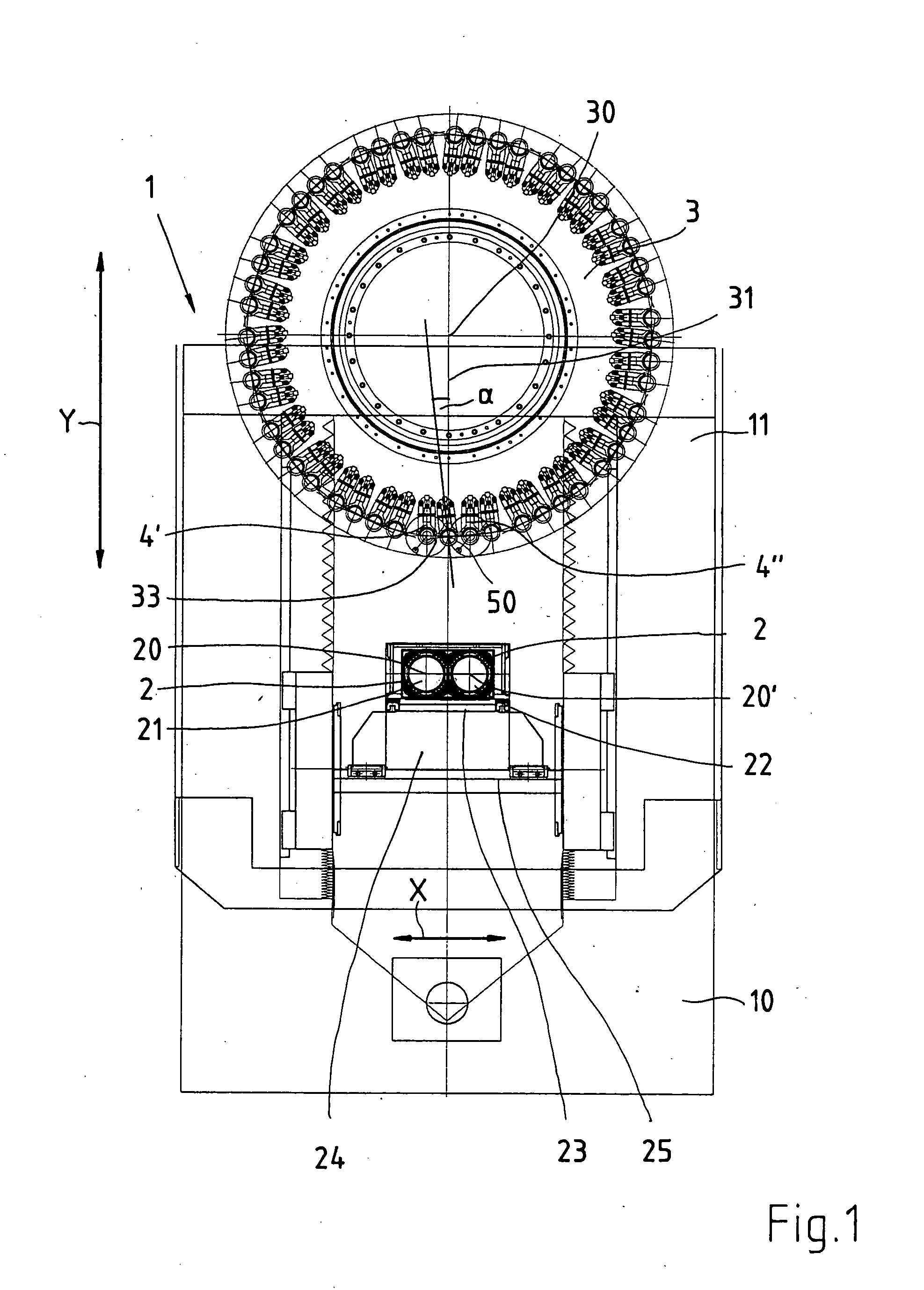
[0078] In FIG. 1 a first modification of the machine tool 1 according to the invention is shown. The machine tool 1 is formed by a machine bed 10, along which in upward direction the machine column 11 extends. The work spindles 2 rest on the machine bed 10. In the example shown here two work spindles are indicated, a first work spindle 21 and a second spindle 22. The two spindles 21, 22 are imbedded in a headstock 23, and can be shifted by the slides 24 on a guide path 25 in X-direction.

[0079] Reference number 20 indicates the spindle axis of the work spindle 2.

[0080] In the example shown here a tool magazine disc 3 is provided which is arranged above the work spindle 2.

[0081] It is an advantage that the tool magazine disc 3 is designed in such a way that it can be shifted here vertically along the drawn Y-axis. By means of this an accordingly expensive compound rest guide in the work spindle can be done without. In order to reach the Y-movement of the tool magazine disc a guide ...


PUM

PropertyMeasurementUnit
Fractionaaaaaaaaaa
Angleaaaaaaaaaa
Angleaaaaaaaaaa

Abstract

The invention refers to a machine tool with only one work spindle which carries and drives an exchangeable machining tool. Furthermore a tool supply is provided which has tool tongs for receiving machining tools. For exchanging and replacing the machining tools a relative movement is provided. It is suggested to share out the tool supply between at least two partial magazines.

Description

[0001] The invention refers to a machine tool with a work spindle which has a tool supply which has tool tongs for receiving machining tools, a relative movement between tool magazine and work spindle being provided for exchanging, respectively replacing, machining tools on the work spindle. BACKGROUND OF THE INVENTION [0002] So-called one-spindle machine tools are sufficiently known. Also multi-spindle machine tools are known. In these in a machine tool a work spindle is provided. The machine tools of this type are often used for cutting machining. The advantage of these machine tools is the high cutting capacity. [0003] For replacing, respectively exchanging, machining tools on the work spindles a procedure known as “pick-up technique” is used. It is known to design the tool magazine stationary for the tool change procedure, and the work spindle moves towards the tool magazine. For putting-in or removing the tool a relative movement between the tool magazine disc and the work spin...

Claims


Application Information

Patent Timeline
IPC IPC(8): B23Q3/155B23Q3/157
CPCB23Q3/15526B23Q3/15706B23Q3/15786Y10T483/1845Y10T409/307784Y10T483/1795B23Q2039/002Y10T483/115B23Q2003/15537B23Q3/15539B23Q11/08B23Q3/15722B23Q39/022B23Q39/04
Inventor LUTZ, HEINRICHKIENLE, ANTON
Owner GROB WERKE BURKHART GROB E K
Why Eureka
Try Eureka