Hydromechanical transmission and control method

a technology of hydromechanical transmission and control method, which is applied in the direction of control devices, vehicle components, gears, etc., can solve the problems of increasing reducing transmission reliability, and other hydromechanical transmissions making unwanted tradeoffs in transmission complexity, packaging efficiency, and operating drive ranges, so as to increase system cost and complexity, reduce transmission reliability, and smooth shifting

Active Publication Date: 2022-10-25
DANA ITAL SRL
View PDF10 Cites 0 Cited by
  • Summary
  • Abstract
  • Description
  • Claims
  • Application Information

AI Technical Summary

Benefits of technology

[0004]The inventors have recognized several drawbacks with Fabry's transmission as well as other hydromechanical transmissions. Fabry's synchronizers, for example, may be susceptible to degradation, which generally decreases transmission reliability. Furthermore, the synchronizing devices increase system cost and complexity. Other hydromechanical transmissions have made unwanted tradeoffs with regard to transmission complexity, packaging efficiency, operational drive ranges, and shifting smoothness.
[0005]To address at least a portion of the abovementioned issues, the inventors have developed a transmission system. The transmission system includes a hydraulic pump and motor. The hydraulic motor is rotationally coupled in parallel with a first and a second planetary gear set. In the system, sun gears of the first and second planetary gear sets are rotationally coupled to the hydraulic motor. Further, in the system, a carrier of the first planetary gear set may be rotationally coupled to a first clutch and a second clutch. Additionally, a ring gear of the second planetary gear set may be rotationally coupled to a third clutch. Providing a transmission with sun gears and clutches with this layout, allows the system to realize a compact design and a targeted number of available drive ranges.
[0006]Further, in one example, the first clutch may be a first forward drive clutch and the second clutch may be a reverse drive clutch arranged adjacent and coaxial with the first forward drive clutch. Positioning the clutches in this manner increases transmission space efficiency while allowing the system to achieve a first forward drive range and a reverse drive range.
[0007]In another example, the transmission system may include a mechanical PTO an input shaft that receives rotational input from a motive power source. Providing the mechanical PTO further increases the system's adaptability and allows the system to be used in a wider variety of vehicle applications, if so desired.

Problems solved by technology

Further, each of the pairs of clutches and synchronizers are spaced away from one another due to the packaging constraints imposed by the transmission assembly.
Fabry's synchronizers, for example, may be susceptible to degradation, which generally decreases transmission reliability.
Furthermore, the synchronizing devices increase system cost and complexity.
Other hydromechanical transmissions have made unwanted tradeoffs with regard to transmission complexity, packaging efficiency, operational drive ranges, and shifting smoothness.

Method used


Image

  • Hydromechanical transmission and control method
  • Hydromechanical transmission and control method
  • Hydromechanical transmission and control method

Examples


Embodiment Construction

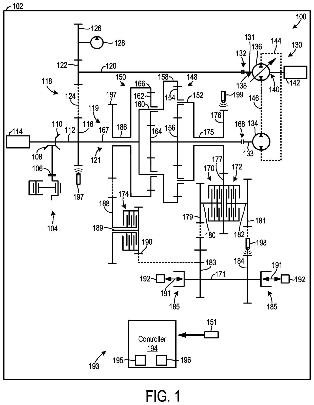
[0021]A hydromechanical transmission and method for operation of the transmission is provided herein. The hydromechanical transmission enables synchronous shifting to occur in a space efficient package. The transmission includes one reverse clutch and two forward clutches coupled in parallel to one another as well as a first and a second planetary gear set to achieve a desired set of operating drive ranges. In one example, the reverse clutch and one of the forward drive clutches may be rotationally coupled to a common shaft. This twin clutch design may enable manufacturing costs to be decreased and enable the transmission to achieve a more compact design. Further, in such an example, the second forward drive clutch may rotate on a shaft offset from the other clutches and planetary assemblies. In this way, the transmission may achieve a targeted degree of drop (e.g., a distance between the input and output interfaces). Further in one example, a hydrostatic assembly in the transmissio...


PUM


Abstract

Methods and systems for a hydromechanical transmission are provided herein. In one example, the transmission system includes a hydraulic pump and a hydraulic motor rotationally coupled in parallel with a first planetary gear set and a second planetary gear set. In the system, sun gears of the planetary gear sets are rotationally coupled to the hydraulic motor, a carrier of the first planetary gear set is rotationally coupled to a first clutch and a second clutch, and a ring gear of the second planetary gear set is rotationally coupled to a third clutch.

Description

TECHNICAL FIELD[0001]The present disclosure relates to a hydromechanical transmission and a method for adjusting transmission drive range.BACKGROUND AND SUMMARY[0002]Hydromechanical transmissions enable performance characteristics (e.g., efficiency, shift quality, drive characteristics, control response, and the like) from mechanical and hydrostatic transmissions to be blended to meet certain design objectives. Some hydromechanical transmissions, referred to in the art as hydromechanical variable transmissions (HVTs), provide continuously variable gear ratios. Hydromechanical transmissions may be particularly desirable due to their efficiency and power take off (PTO) capabilities. Vehicles used in industries such as agriculture, construction, mining, material handling, oil and gas, and the like have therefore made use of HVTs.[0003]U.S. Pat. No. 7,530,914 B2 to Fabry et al. teaches a hydromechanical transmission with two synchronizers and two clutches. The synchronizing devices and ...

Claims


Application Information

Patent Timeline
Patent Type & Authority Patents(United States)
IPC IPC(8): F16H47/04F16H37/08B60K17/28B60K17/10
CPCF16H47/04B60K17/105B60K17/28F16H37/084F16H2037/0886B60K17/02B60K17/10
Inventor PROFUMO, GIOVANNIDALLA PALMA, LORENZO
Owner DANA ITAL SRL
Why Eureka
Try Eureka