Device for generating a massage stream in a sanitary tub

Inactive Publication Date: 2005-11-03
FRANZ KALDEWEI
View PDF5 Cites 3 Cited by
  • Summary
  • Abstract
  • Description
  • Claims
  • Application Information

AI Technical Summary

Benefits of technology

[0005] It is therefore an object of the invention to provide a device which allows setting the direction of the stream of water exiting from the device, without a jet-shaped n

Problems solved by technology

The arrangement is complicated in terms of design and assembly technology.
Furtherm

Method used


Image

  • Device for generating a massage stream in a sanitary tub
  • Device for generating a massage stream in a sanitary tub
  • Device for generating a massage stream in a sanitary tub

Examples


Embodiment Construction

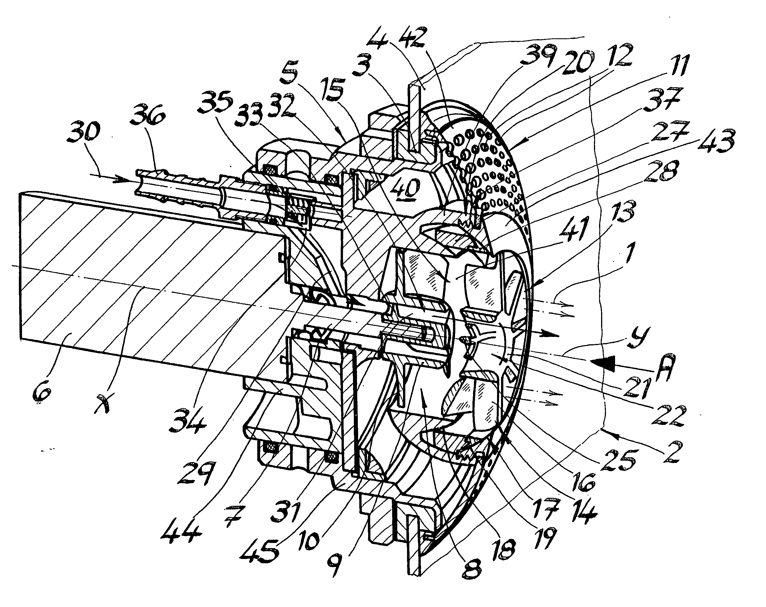
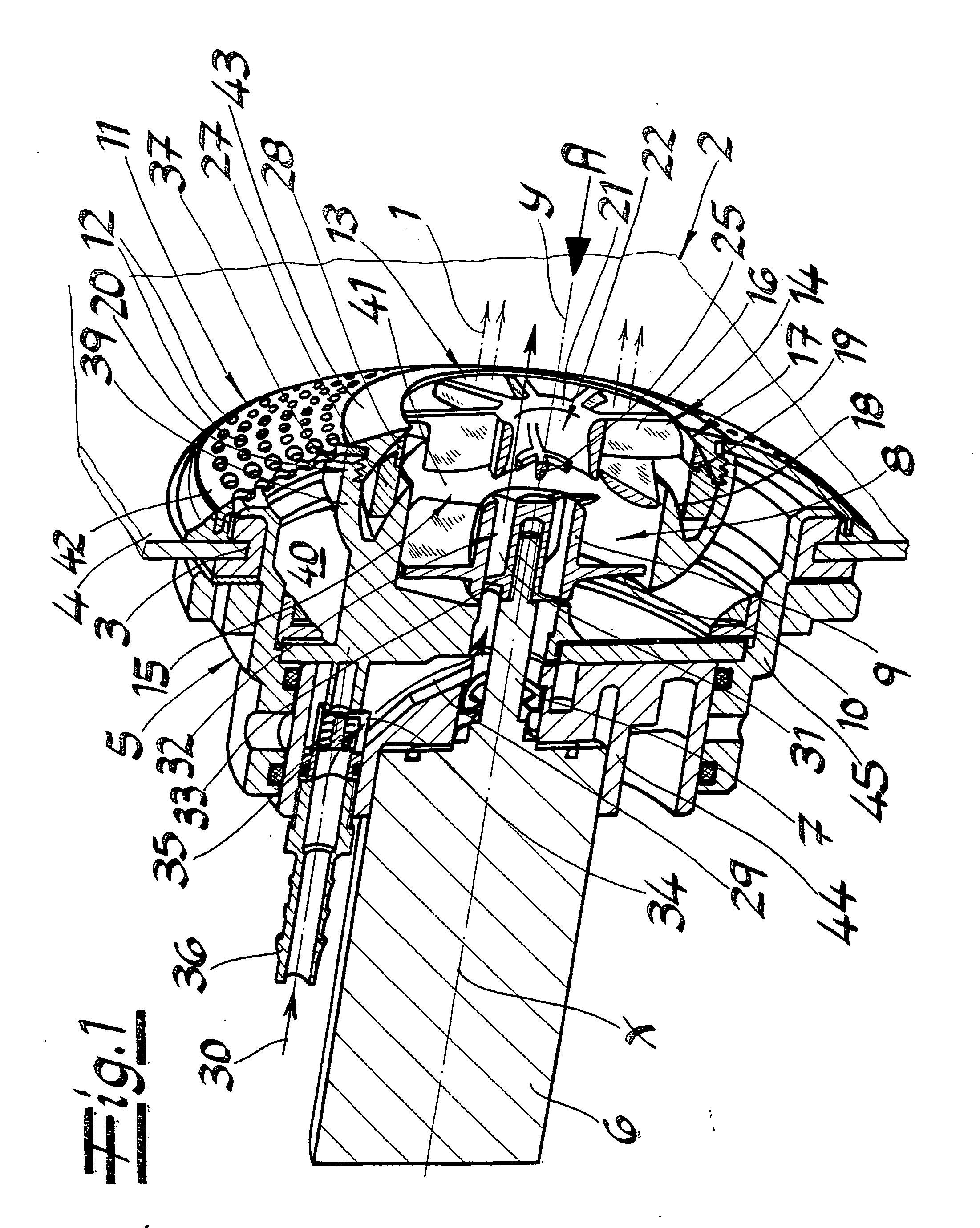
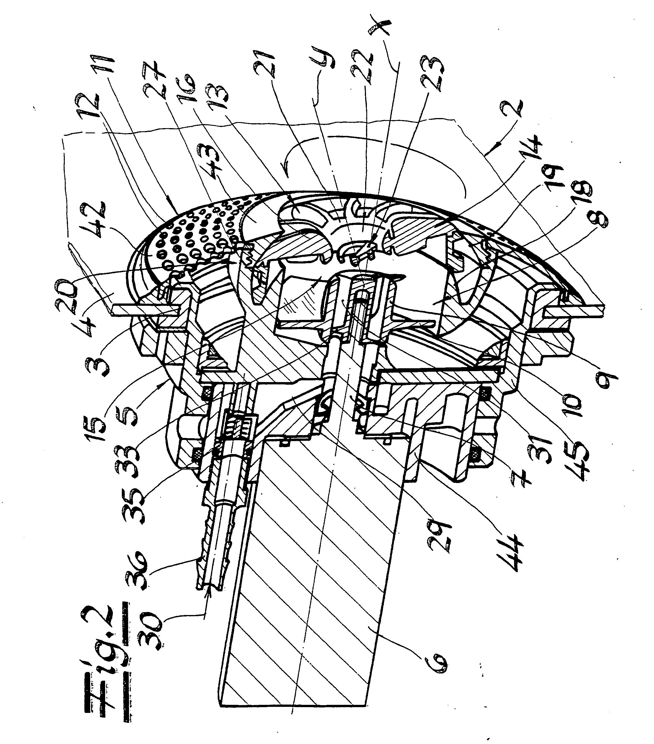
[0015] Referring now in detail to the drawings, the figures show a device for generating a massage stream 1 in a sanitary tub 2, having an accommodation device 5 that can be attached to an opening 3 in tub body 4, to accommodate an electric motor 6 having a drive shaft 7, a propeller 8 having a hub 9 attached to the drive shaft 7 in overhung manner. There are vanes 10 arranged radially about hub 9, and a rosette 11 arranged on the accommodation device 5, positioned within sanitary tub 2, having edge-side inflow openings 12, as well as a center outlet opening 13. Rosette 11 is configured in two parts and comprises an outer ring 42 having inflow openings 12, as well as an inner attachment ring 43 having outlet opening 13, which is connected with outer ring 42. Propeller 8 draws in water located in sanitary tub 2, through inflow openings 12, and subsequently transports the water back into sanitary tub 2 through a guide element 14 arranged in outlet opening 13, which element can pivot r...


PUM


Abstract

A device for generating a massage stream in a sanitary tub has an accommodation device that can be attached to an opening in the tub body of the sanitary tub, for accommodating an electric motor having a drive shaft, a propeller having a hub attached to the drive shaft and vanes arranged radially about the hub. There is a rosette arranged on the accommodation device, positioned within the sanitary tub, having edge-side inflow openings, as well as a central outlet opening. The propeller draws water located in the sanitary tub in through the inflow openings, and subsequently transports it back into the sanitary tub, through a guide element arranged in the outlet opening, which can be pivoted relative to the hub axis. The guide element is configured as a guide vane ring and has a ring-shaped bearing shell at the outer end of the guide vanes. The shell moves between a glide surface of the accommodation device that is configured as a sphere surface segment, and a concave contact surface of the rosette.

Description

BACKGROUND OF THE INVENTION [0001] 1. Field of the Invention [0002] The invention relates to a device for generating a massage stream in a sanitary tub. In particular, the invention relates to a device having an accommodation device that can be attached to an opening in the tub body of the sanitary tub for accommodating an electric motor having a drive shaft, a propeller having a hub attached to the drive shaft and vanes arranged radially about the hub, and a rosette arranged on the accommodation device, positioned within the sanitary tub, having edge-side inflow openings, as well as a central outlet opening. The propeller draws water located in the sanitary tub in through the inflow openings, and subsequently transports it back into the sanitary tub, through a guide element arranged in the outlet opening, which can be pivoted relative to the hub axis. [0003] 2. The Prior Art [0004] A device having the characteristics described above is discussed in German Patent No. DE 198 34 341 C...

Claims


Application Information

Patent Timeline
IPC IPC(8): A47K3/00A61H23/00A61H33/00A61H33/02
CPCA61H33/027A61H2201/1207A61H2033/023A61H33/6063
Inventor SCHLIEF, DIRK
Owner FRANZ KALDEWEI
Why Eureka
Try Eureka