Displacement sensor
- Summary
- Abstract
- Description
- Claims
- Application Information
AI Technical Summary
Benefits of technology
Problems solved by technology
Method used
Image
Examples
first embodiment
(First Embodiment)
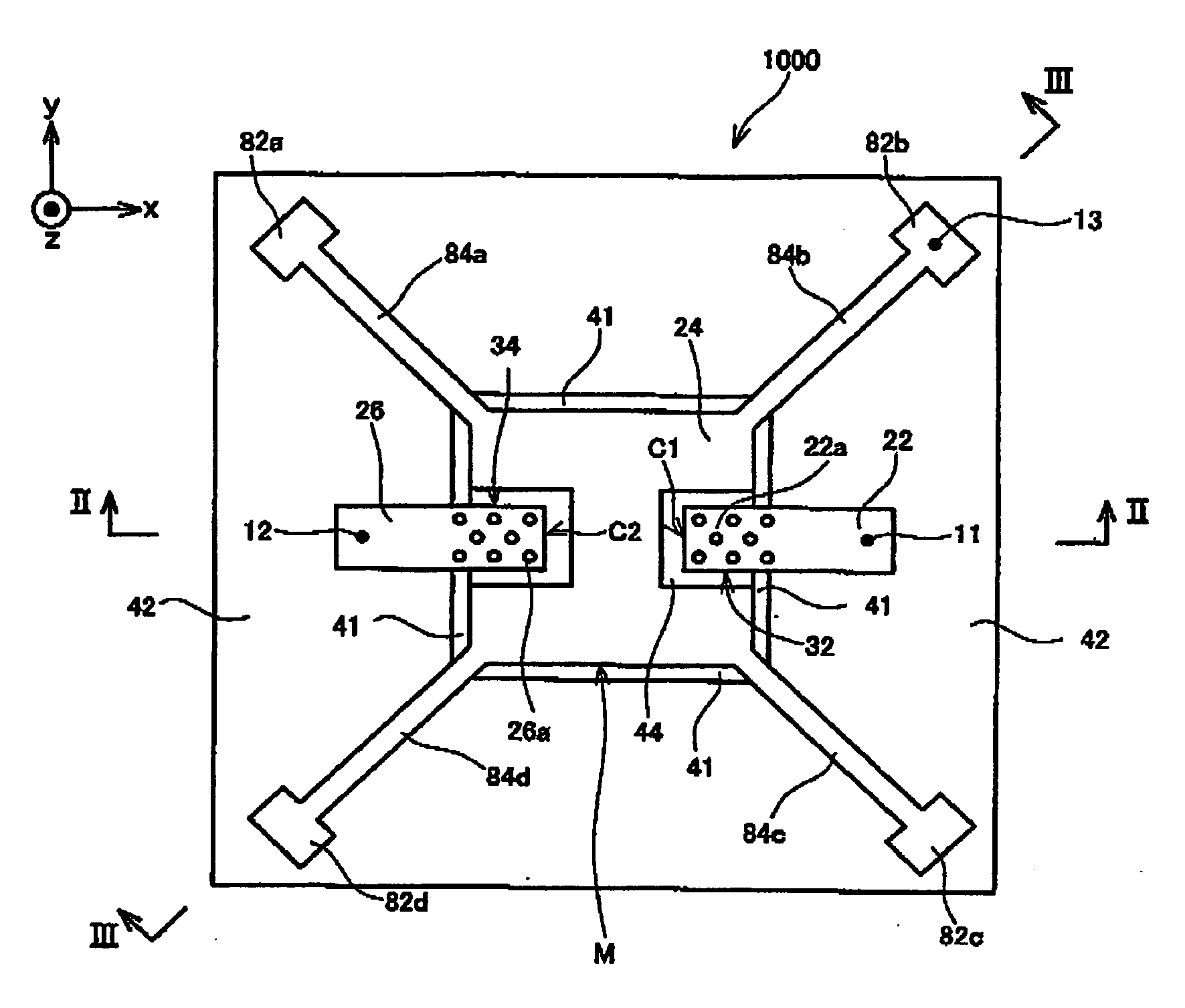
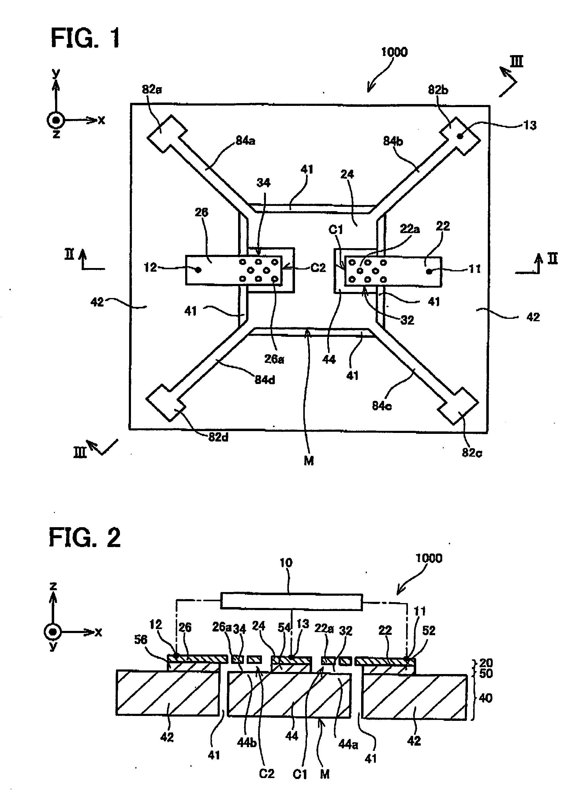
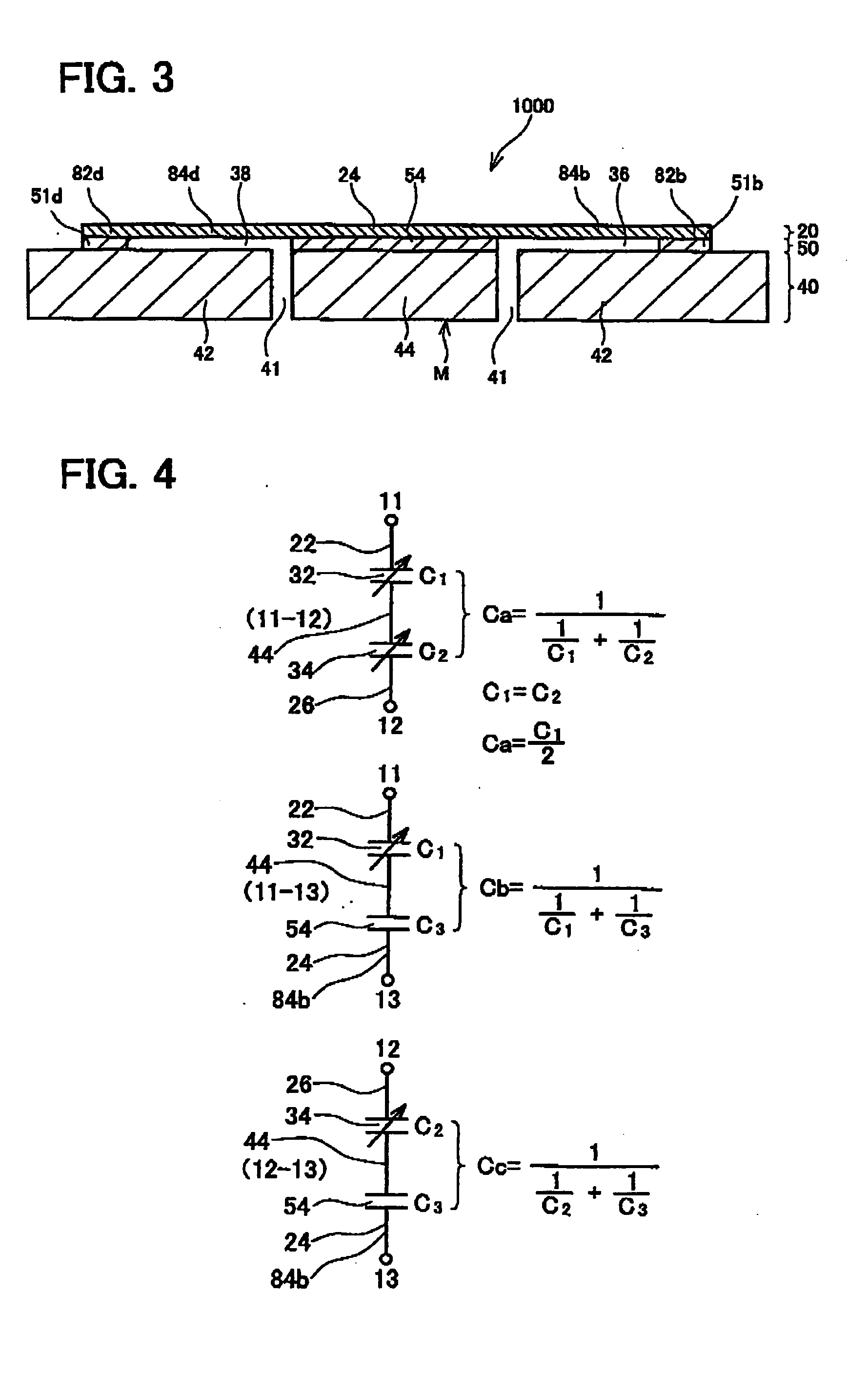
[0101] FIGS. 1 to 3 schematically show the structure of an acceleration sensor 1000. FIG. 1 is a plan view of the acceleration sensor 1000. FIG. 2 corresponds to a longitudinal section along a line II-II of FIG. 1, and FIG. 3 corresponds to a longitudinal section along a line III-III of FIG. 1. The acceleration sensor 1000 is used to measure acceleration in a z direction (a direction perpendicular to the face of the page in FIG. 1, and the up-down direction of the page in FIGS. 2 and 3).
[0102] First, a simple description will be given of the structure of the acceleration sensor 1000 with reference to FIGS. 1 to 3. The acceleration sensor 1000 is made of an SOI (Silicon on Insulator) having stacked layers comprising a conductive lower layer 40 formed from monocrystal silicon, an insulating layer 50 formed from silicon oxide stacked on the conductive lower layer 40, and a conductive upper layer 20 formed from monocrystal silicon stacked on the insulating layer 50. T...
second embodiment
(Second Embodiment)
[0122]FIGS. 5 and 6 schematically show the structure of an acceleration sensor 1100 of a second embodiment. A description might be omitted of components configured identically to those of the first embodiment. The acceleration sensor 1100 performs detection by differentiating the degree of change in electrostatic capacity of a pair of condensers C1 and C4.
[0123] As shown in FIGS. 5 and 6, a conductive upper layer 20 of the acceleration sensor 1100 is provided with a first upper portion 22 forming one of electrodes of a condenser C1. The first upper portion 22 extends from a position above a first lower region 44 to a position above a second lower region 42. A first fixing insulating layer 52 is formed between the first upper portion 22 and the second lower region 42. An insulating layer 50 is not formed between the first lower region 44 and a first extending portion 22a of the first upper portion 22. A first condenser C1 is formed from the first extending portion...
third embodiment
(Third Embodiment)
[0134]FIGS. 8 and 9 schematically show the structure of an acceleration sensor 1200 of a third embodiment. The acceleration sensor 1200 is a variant of the acceleration sensor 1100 of the second embodiment.
[0135] In the acceleration sensor 1200, as shown in FIGS. 8 and 9, a region that includes a second opposing portion 46a—this being opposite a second extending portion 24a of a second upper portion 24—(hereafter, this region will be termed a second opposing lower region 46) is insulated from a remaining portion of a second lower region 42. This insulation is attained by means of a slit 49 that penetrates a conductive lower layer 40. The slit 49 is connected with a dividing groove 41.
[0136] As shown in FIGS. 8 and 9, the second opposing lower region 46 is fixed to the second lower region 42 via a portion 53 of an insulating layer 50. Although the second opposing lower region 46 is electrically separated from the second lower region 42 by the slit 49, it is mechan...
PUM
 Abstract
Description
Claims
Application Information
 - R&D
- Intellectual Property
- Life Sciences
- Materials
- Tech Scout
- Unparalleled Data Quality
- Higher Quality Content
- 60% Fewer Hallucinations
Browse by: Latest US Patents, China's latest patents, Technical Efficacy Thesaurus, Application Domain, Technology Topic, Popular Technical Reports.
© 2025 PatSnap. All rights reserved.Legal|Privacy policy|Modern Slavery Act Transparency Statement|Sitemap|About US| Contact US: help@patsnap.com


