
Solid rubber packer for a rotating control device

a control device and solid rubber technology, applied in the direction of sealing/packing, mechanical equipment, borehole/well accessories, etc., can solve the problems of hazard to the drilling crew and equipment, prone to maintenance of rotating equipment, and large expenditure of manpower and equipment for drilling wellbore hydrocarbons

Inactive Publication Date: 2005-11-03
WEATHERFORD TECH HLDG LLC
View PDF33 Cites 81 Cited by
  • Summary
  • Abstract
  • Description
  • Claims
  • Application Information

AI Technical Summary

Problems solved by technology

Drilling a wellbore for hydrocarbons requires significant expenditures of manpower and equipment.
Rotating equipment is particularly prone to maintenance as the drilling environment produces abrasive cuttings detrimental to the longevity of rotating seals, bearings, and packing elements.
In many instances, the formations produce gas or fluid pressure that may be a hazard to the drilling crew and equipment unless properly controlled.
Even though an effective seal is formed between the BOP and the tubular, the spherical element may be damaged as the tubular is rotated and tubular joints are stripped through a closed BOP.
More specifically, as the spherical sealing element is urged against the plurality of flanged inserts, the sealing element tends to extrude under the noses of the flanged inserts where it is restricted from movement and forced into the path of the moving tool joint which results in damage to the spherical sealing element.
However, the active seal arrangement in the conventional rotating control head has a tendency to leak at the seal as the string of drill pipe is axially forced through the rotating control head which may result in eventual failure of the rotating control head.
Additionally, as the string of drill pipe is axially and slidably forced through the rotating control head, the axial movement of the drill pipe causes wear and tear on the bearing and seal assembly and subsequently requires repair.
The process is time consuming and can be dangerous.

Method used


Image

  • Solid rubber packer for a rotating control device
  • Solid rubber packer for a rotating control device
  • Solid rubber packer for a rotating control device

Examples


Embodiment Construction

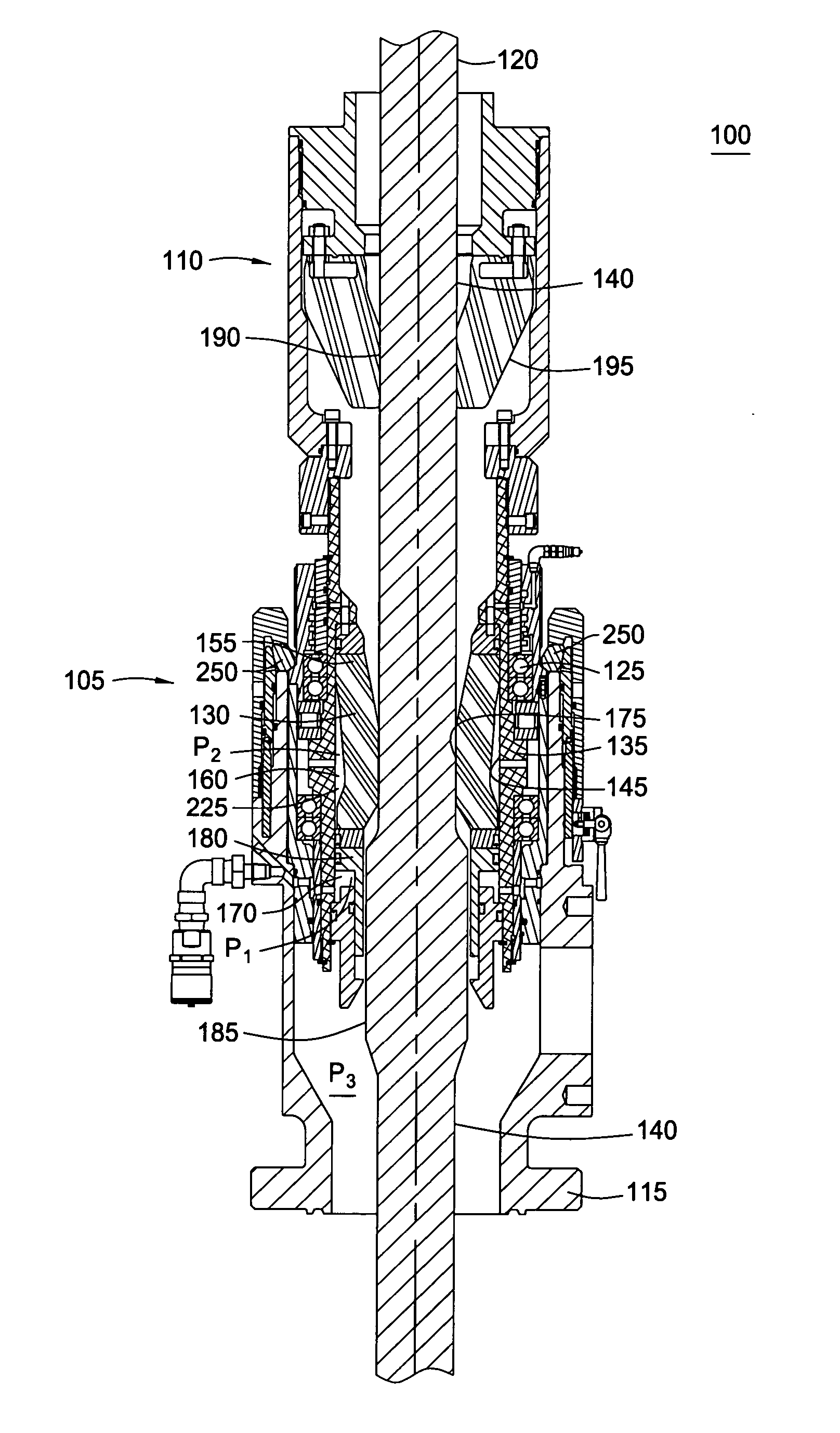
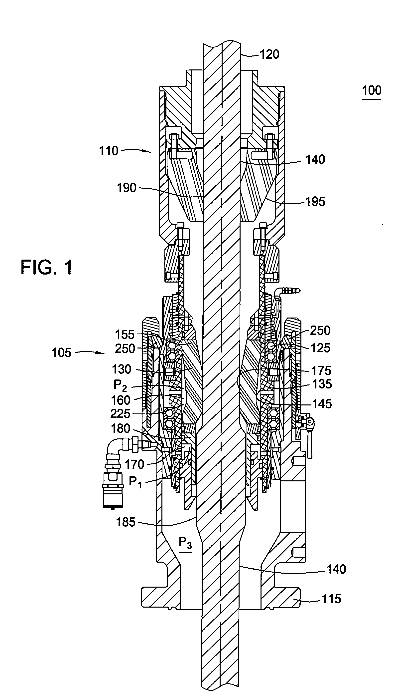
[0025] The present invention generally relates to a rotating control head for use with a drilling rig. Typically, an internal portion of the rotating control head is designed to seal around a rotating tubular string and rotate with the tubular string by use of an internal sealing element, and rotating bearings. Additionally, the internal portion of the rotating control head permits the tubular string to move axially and slidably through the rotating control head. FIGS. 1 and 9 generally describe the rotating control head and FIGS. 2-8 describe several embodiments of a sealing assembly. To better understand the novelty of the present invention and the methods of use thereof, reference is hereafter made to the accompanying drawings.

[0026]FIG. 1 is a cross-sectional view illustrating the rotating control head 100 in accordance with the present invention. The rotating control head 100 includes an active seal assembly 105 and a passive seal assembly 110. Each seal assembly 105, 110 incl...


PUM


Abstract

A seal assembly for use with a rotating control head is provided. The seal assembly includes a rotatable member and a cavity formed between the rotatable member and a tubular radially inwardly disposed from the rotatable member. The cavity having a first surface and a second surface. The seal assembly further includes a seal member having a first end and a second end disposed between the first surface and the second surface of the cavity and sealable with the tubular between the first and the second ends due to deformation of the seal member.

Description

CROSS-REFERENCE TO RELATED APPLICATIONS [0001] This application is a continuation-in-part of co-pending U.S. patent application Ser. No. 10 / 285,336, filed on Oct. 31, 2002, which is herein incorporated by reference.BACKGROUND OF THE INVENTION [0002] 1. Field of the Invention [0003] Embodiments of the present invention generally relate to wellbore operation. More particularly, the invention relates to a method of use and an apparatus for sealing around a tubular. Still more particularly, the invention relates to a seal assembly for use in a control head. [0004] 2. Description of the Related Art [0005] Drilling a wellbore for hydrocarbons requires significant expenditures of manpower and equipment. Thus, constant advances are being sought to reduce any downtime of equipment and expedite any repairs that become necessary. Rotating equipment is particularly prone to maintenance as the drilling environment produces abrasive cuttings detrimental to the longevity of rotating seals, bearing...

Claims


Application Information

Patent Timeline
Patent Type & Authority Applications(United States)
IPC IPC(8): E21B33/08
CPCE21B33/085F16J15/025F16J15/3236F16J15/3216F16J15/3224F16J15/3208E21B33/03E21B33/128E21B33/1285F16J15/16
Inventor BAILEY, THOMAS F.CHAMBERS, JAMES W.GRAVOUIA, MARK F.
Owner WEATHERFORD TECH HLDG LLC
Features
  • Generate Ideas
  • Intellectual Property
  • Life Sciences
  • Materials
  • Tech Scout
  • Unparalleled Data Quality
  • Higher Quality Content
  • 60% Fewer Hallucinations
Learn More