Electronic device holder on bicycle

a technology for electronic devices and bicycles, applied in the direction of supporting devices, machine supports, bicycle equipment, etc., can solve the problems of increasing the use and purchase cost structure, increasing the willingness to purchase electronic equipment holders, and increasing the cost of use and purchase costs, so as to reduce the cost structure, double the positioning force, and cost-effective

Inactive Publication Date: 2015-04-07
WU PAO KUNG
View PDF23 Cites 95 Cited by
  • Summary
  • Abstract
  • Description
  • Claims
  • Application Information

AI Technical Summary

Benefits of technology

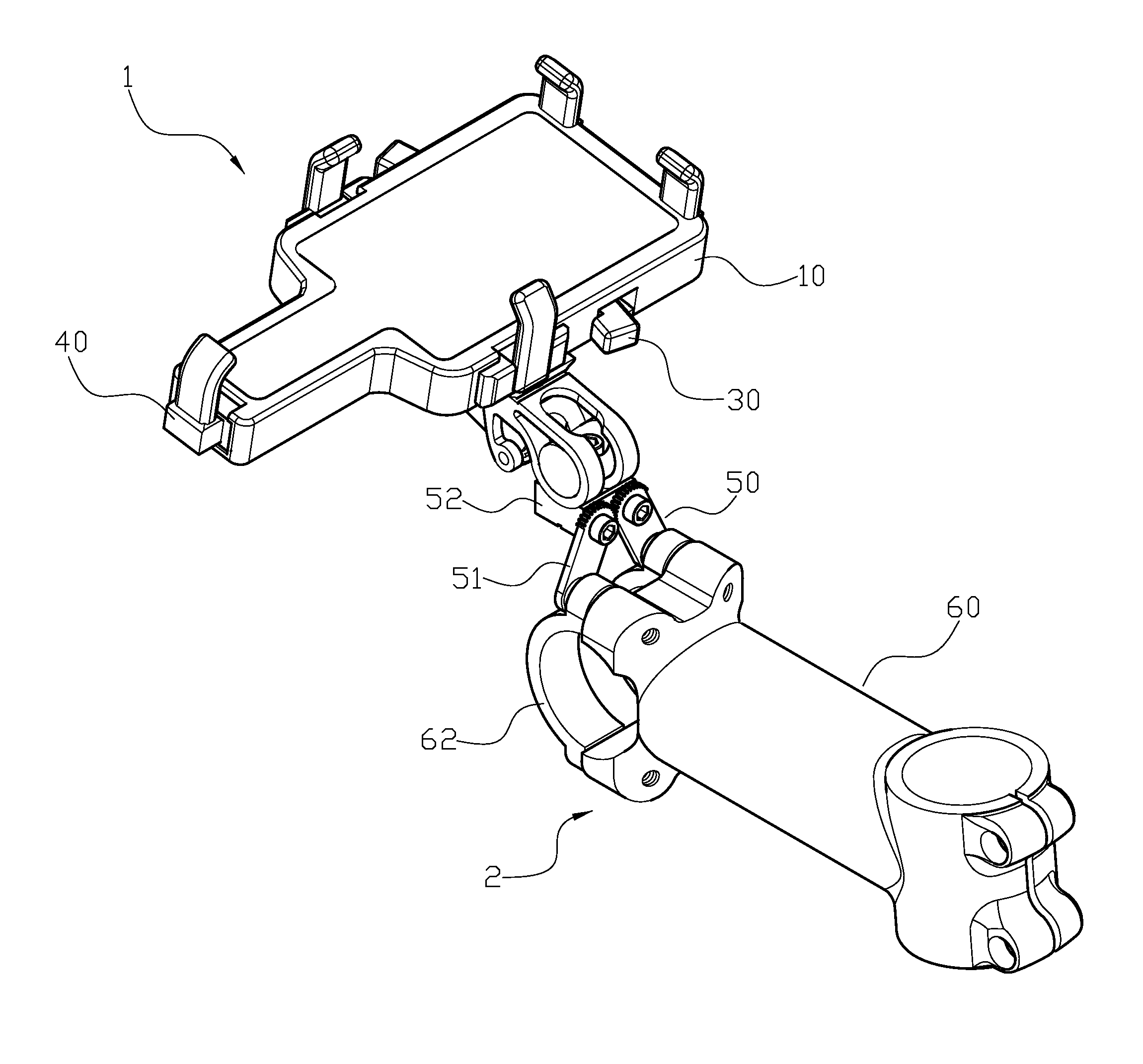
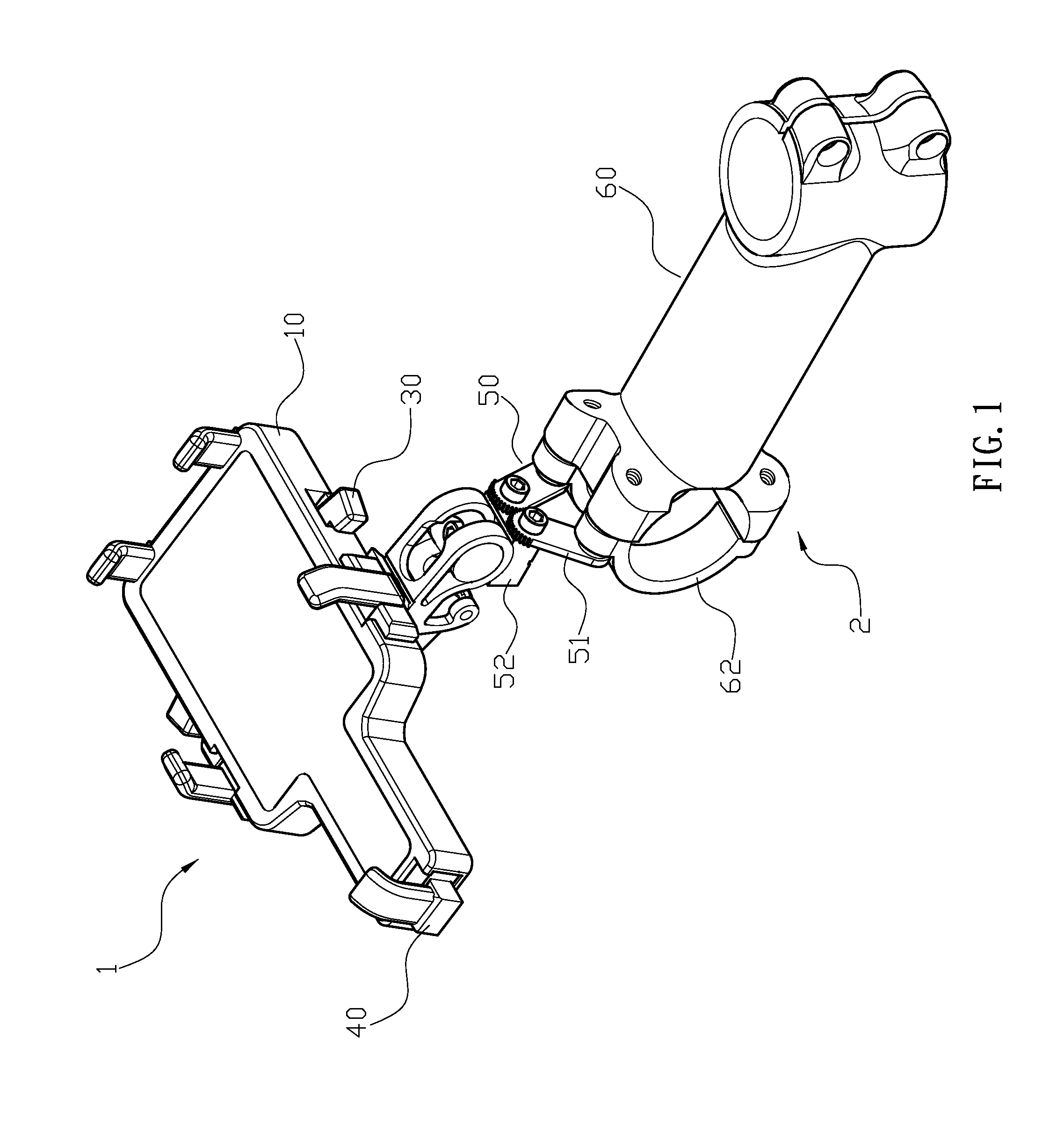
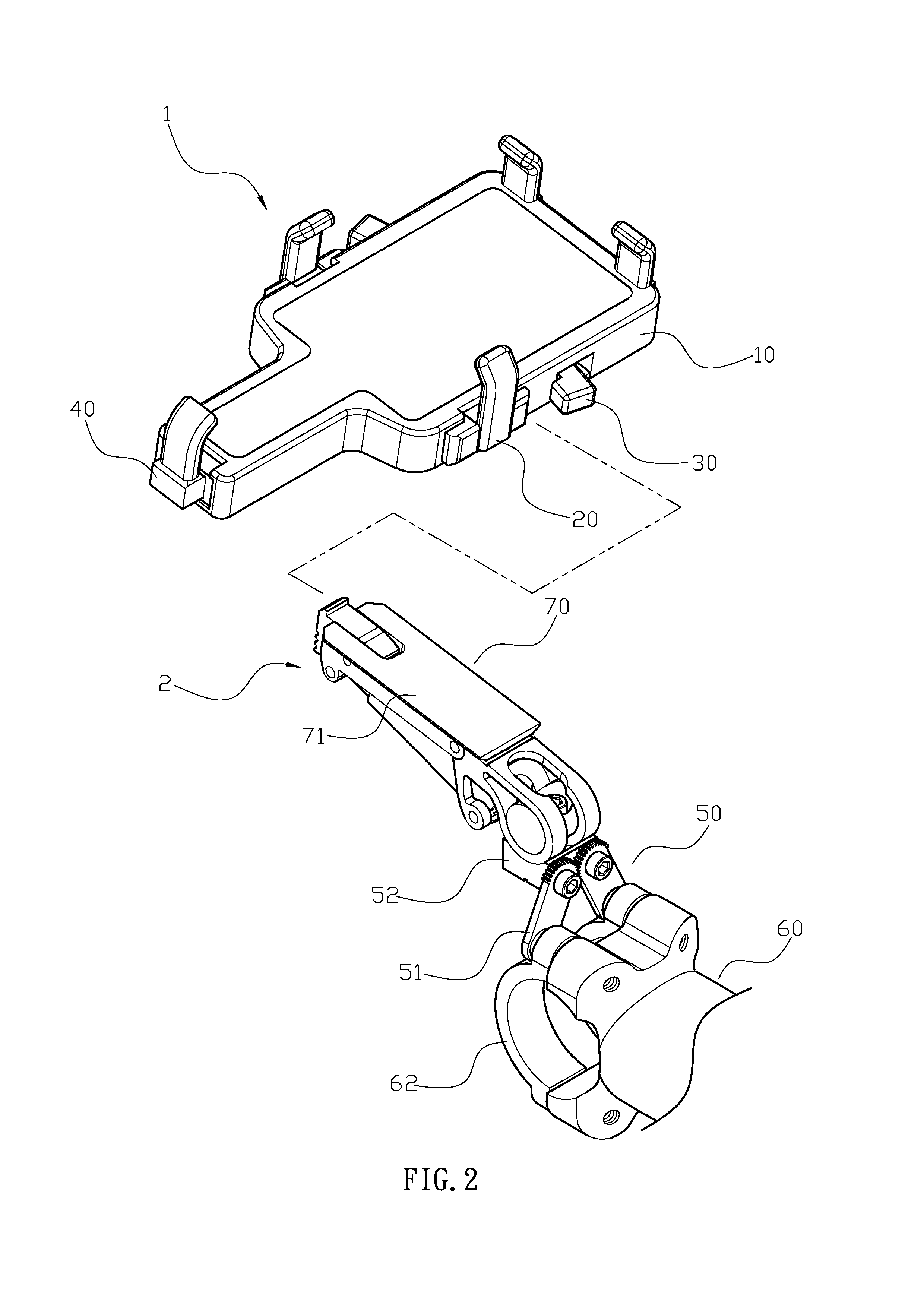
[0008]Comparing with prior arts, the present invention is advantageous because (i) the present invention is the structural improvement on bicycle clamping device for electronic gadgets, its fine adjustment unit provide the body to stabilize device, coupled with a fixed risers installed on the holder. When desire to use on other types of bicycles, or when user want to replace the standpipe bicycle frame structure, are assembled for longer usage to adjust the size of fine adjustment unit corresponds to the structure of the standpipe. Therefore, the holder with fine adjustment unit is applicable to various types of risers, adding to the convenience of the use of holder without an additional correspondence or to other types of bicycle purchase for its additional standpipe fittings, effectively reducing the cost structure, and is cost-effective; (ii) the structural improvement on bicycle clamping device for electronic gadgets, wherein the distance which the movable clamp

Problems solved by technology

However, the conventional structure described above is to the practical applications, which still have problems as followed: (a) it is not practical due to the variety types of bicycle in the market, the standpipe appearance and size of many, causing the electronic equipment unable to fully placed it onto the frame body, whereas the riders has to purchase an extra connection fitting to further utilize onto all kinds of risers and assembly.
Moreover, when the frame to replace the vertical tube is attached to the frame body or wishing to ride on the other bicycle, the user have to purchase another piece to be assembled with the usage, increasing the use and purchase cost structure is

Method used


Image

  • Electronic device holder on bicycle
  • Electronic device holder on bicycle
  • Electronic device holder on bicycle

Examples


Embodiment Construction

[0024]The detailed description set forth below is intended as a description of the presently exemplary device provided in accordance with aspects of the present invention and is not intended to represent the only forms in which the present invention may be prepared or utilized. It is to be understood, rather, that the same or equivalent functions and components may be accomplished by different embodiments that are also intended to be encompassed within the spirit and scope of the invention.

[0025]Unless defined otherwise, all technical and scientific terms used herein have the same meaning as commonly understood to one of ordinary skill in the art to which this invention belongs. Although any methods, devices and materials similar or equivalent to those described can be used in the practice or testing of the invention, the exemplary methods, devices and materials are now described.

[0026]All publications mentioned are incorporated by reference for the purpose of describing and disclos...


PUM


Abstract

An electronic device holder on a bicycle may include a frame body and a standpipe connection seat, and the frame body is composed of a body, a clamping device, two rotation controls and the nip unit pressing as the combination. The standpipe connection seat is provided with a fine adjustment unit, and the fine adjustment unit, is located on the beam of the glove with the set of risers, and provided to assemble for the anchor of body.

Description

FIELD OF THE INVENTION[0001]The present invention relates to a structure improvement on bicycle clamp holder with electronic gadgets, especially with an adjustable clamping distance, and the clamp holder will be suitable for a variety of models to hold its electronic gadgets for bicycle riders, as structure reformers.BACKGROUND OF THE INVENTION[0002]Conventionally, the purpose of bicycle riding experience is not only to be limited as to travel, and fitness, but, when moving forward is simply relied on human stampede, it will be no need for any additional emissions or caused fuel problems. Because there are so many benefits counting down just for riding a bicycle, the governments worldwide and the trend of sports biking in recent years rushing towards the world, are pleased to see its blooming industry, hoping to reduce the usage of automobile and motorcycle with bicycles. On the other hand, due to a variety of electronic devices blooming popularly (such as smart phones, tablet PCs, ...

Claims


Application Information

Patent Timeline
IPC IPC(8): B62J11/00
CPCB62J11/00F16M13/00F16B2/12F16M11/041F16M11/10F16M13/02B62J50/225
Inventor WU, PAO-KUNG
Owner WU PAO KUNG
Why Eureka
Try Eureka