Adjustable basket vibratory separator

Active Publication Date: 2005-11-03
VARCO I P INC
View PDF89 Cites 26 Cited by
  • Summary
  • Abstract
  • Description
  • Claims
  • Application Information

AI Technical Summary

Benefits of technology

[0016] The present invention, in certain embodiments, teaches a vibratory separator (in one particular aspect, a shale shaker) which has sensing apparatus for sensing parameters indicative of the level of fluid or material on a screen or screen assembly supported by the separator and, therefore, for indicating the extent of a beach area on the screen or screen assembly. In one aspect, a screen or screen assembly itself (or a screen on holding structure) is able to be inclined to a desired angle to adjust the extent of a beach area adjacent an exit end of a screen. A beach area is an area adjacent a screen's exit end with two boundary s

Problems solved by technology

Fluid or material that is too deep may not be adequately filtered.
Fluid or material that is too shallow may flow across a screen too quickly or without sufficient weight to be filtered adequately.
The large undesirable particles may include drilling cuttings and debris picked up in the drilling process.
The scre

Method used


Image

  • Adjustable basket vibratory separator
  • Adjustable basket vibratory separator
  • Adjustable basket vibratory separator

Examples


Example

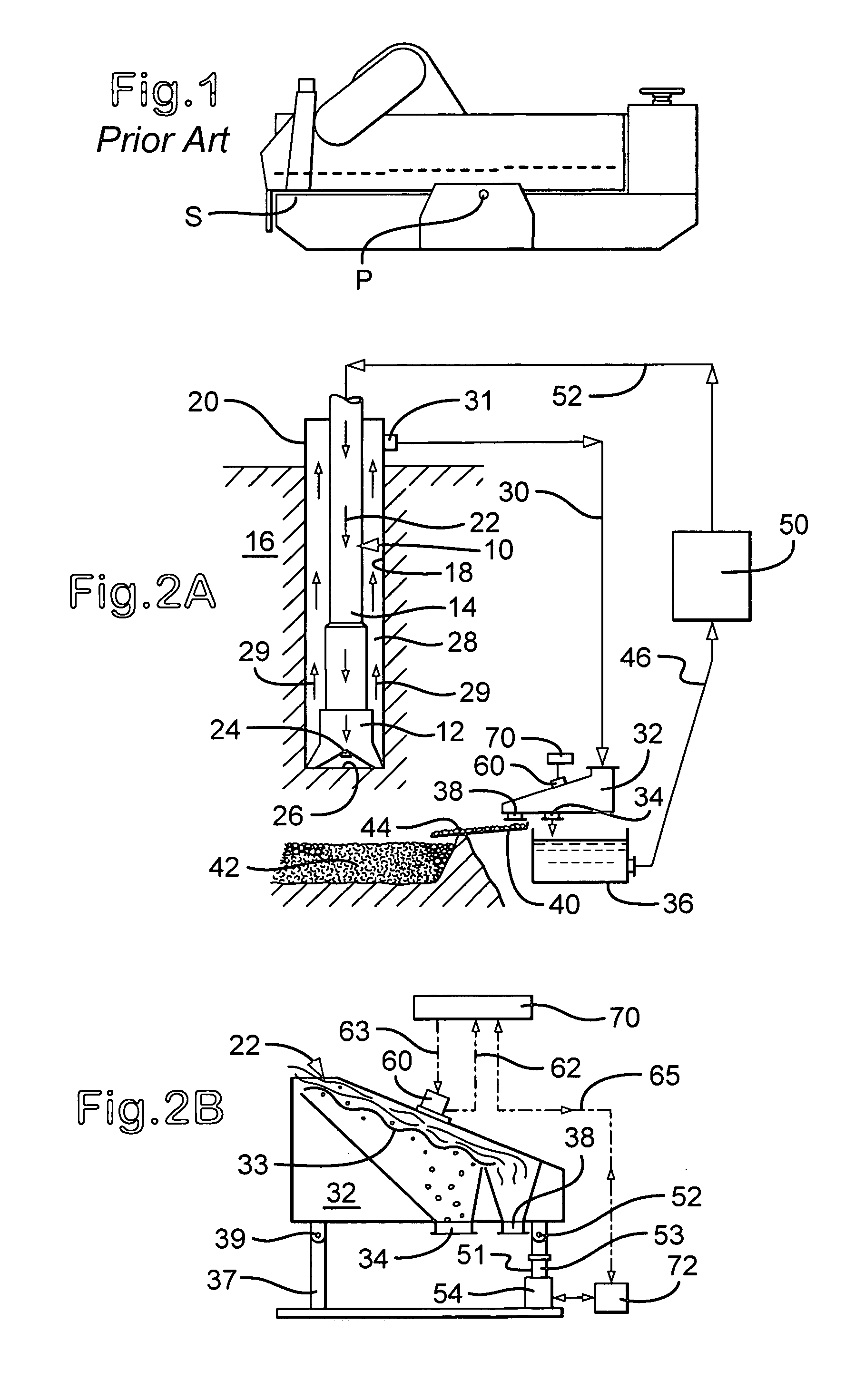
[0049] Referring now to FIGS. 2A and 2B, a drilling system 10 according to the present invention includes a rotary bit 12 attached to the lower end of a length of hollow drill pipe 14 suspended from a drilling derrick (not shown).

[0050] The drill pipe 14 and attached drill bit 12 are rotated to cut into the subsurface formation 16 to form a wellbore 18. The drill pipe 14 passes through a wellhead assembly 20 located at the surface. The wellhead assembly 20 controls flow of drilling fluid into the well. During the drilling of the well, a drilling fluid 22 commonly referred to as drilling mud is pumped down the interior of the hollow drill pipe 14. The drilling mud exits jets such as jet 24 in drill bit 12 and impinges upon a bottom 26 of the well bore 18. The drilling fluid exiting the jets 24 flushes away from the bottom 26 of the wellbore 18 the cuttings or particles generated as the drill bit 12 cuts into the earthen formation 16. A stream of drilling mud 22 then carries the cutt...


PUM

PropertyMeasurementUnit
Forceaaaaaaaaaa
Angleaaaaaaaaaa
Frequencyaaaaaaaaaa

Abstract

A vibratory separator having a base, a basket movably mounted on the base and for supporting screen apparatus for treating material introduced into the vibratory separator, the basket on a base and pivotable with respect thereto, vibratory apparatus connected to the basket for vibrating the basket, screen apparatus supported by the basket, the material flowing onto the screen apparatus for treatment, angle adjustment apparatus connected to the basket for adjusting angle of the basket, sensor apparatus for sensing a parameter indicative of basket angle and for providing a signal corresponding to said basket angle, control apparatus for receiving signals from the sensor apparatus and for controlling basket angle based on said signals, the angle adjustment apparatus, in one particular aspect, including a rocker arm assembly with a first pivotable end.

Description

RELATED APPLICATION [0001] This is a continuation-in-part of U.S. application Ser. No. 10 / 835,256 filed Apr. 29, 2004, which is incorporated fully herein.BACKGROUND OF THE INVENTION [0002] 1. Field of The Invention [0003] This invention is directed to vibratory separators; to apparatuses and methods for sensing fluid levels in such separators; and to apparatuses and methods for adjusting such levels and for adjusting the extent of a beach area on a screen. [0004] 2. Description of Related Art [0005] In many prior art vibratory separators and shale shakers a pool or mass of fluid or material is formed on top of one or more screens or screen assemblies which are used to filter material introduced to the separator or shaker. The depth of this fluid or material can affect efficient operation of the separator or shaker. Fluid or material that is too deep may not be adequately filtered. Fluid or material that is too shallow may flow across a screen too quickly or without sufficient weight...

Claims


Application Information

Patent Timeline
IPC IPC(8): B01D33/03B07B1/00B07B1/42B07B1/46B07B1/49
CPCB01D33/0376B07B1/42B07B1/4609B07B2230/01B01D33/37B01D33/807
Inventor STONE, LYNDONSCOTT, ERICPADOLINO, NORMANMCDONOUGH, KEVIN T.SEYFFERT, KENNETH W.MCCLUNG, GUY L. III
Owner VARCO I P INC
Why Eureka
Try Eureka