
Electric motor, electric power steering apparatus equipped with the motor, and wire winding method for the motor

a technology for electric steering and motors, which is applied in windings, mechanical energy handling, magnetic circuit shapes/forms/construction, etc. it can solve the problems of increased ineffective wire length, increased and large space requirements, so as to reduce crossover wires and reduce overlapping of connecting lines , the effect of enhancing the output torque of the motor

Inactive Publication Date: 2005-11-03
HONDA MOTOR CO LTD
View PDF8 Cites 81 Cited by
  • Summary
  • Abstract
  • Description
  • Claims
  • Application Information

AI Technical Summary

Benefits of technology

[0011] In view of the foregoing, it is an object of the present invention to provide an improved electric motor which is suitable for use in, for example, an electric power steering apparatus and which is small in size, easy to assemble and yet can output greater torque, as well as a novel wire winding method for the motor.
[0016] The first-aspect arrangements identified above can significantly reduce the crossover wire portion, reduce overlapping of the connecting lines and enhance the output torque of the motor. Further, layout and assembly of various components of the motor can be greatly facilitated. The second-aspect arrangements identified above can facilitate the formation of the coil windings. Further, the electric power steering apparatus equipped with the electric motor of the present invention can impart a steering assist force more appropriately, thereby improving a steering feel.
[0017] Furthermore, the wire winding method of the present invention can significantly reduce the crossover wire portion, reduce overlapping of the connecting lines and enhance the output torque of the motor.

Problems solved by technology

Thus, crossover wire portion has to have a long length, which would result in an increased ineffective wire length.
Further, because the wire connections and center points are located on the same side of the tooth portions, a great space is required.
However, in this case too, wire connections and center points are located on the same side of the tooth portions, a great space is required due to overlapping between the wire connections.
Besides, layout and assembly of the components of the motor tend to be difficult.

Method used


Image

  • Electric motor, electric power steering apparatus equipped with the motor, and wire winding method for the motor
  • Electric motor, electric power steering apparatus equipped with the motor, and wire winding method for the motor
  • Electric motor, electric power steering apparatus equipped with the motor, and wire winding method for the motor

Examples


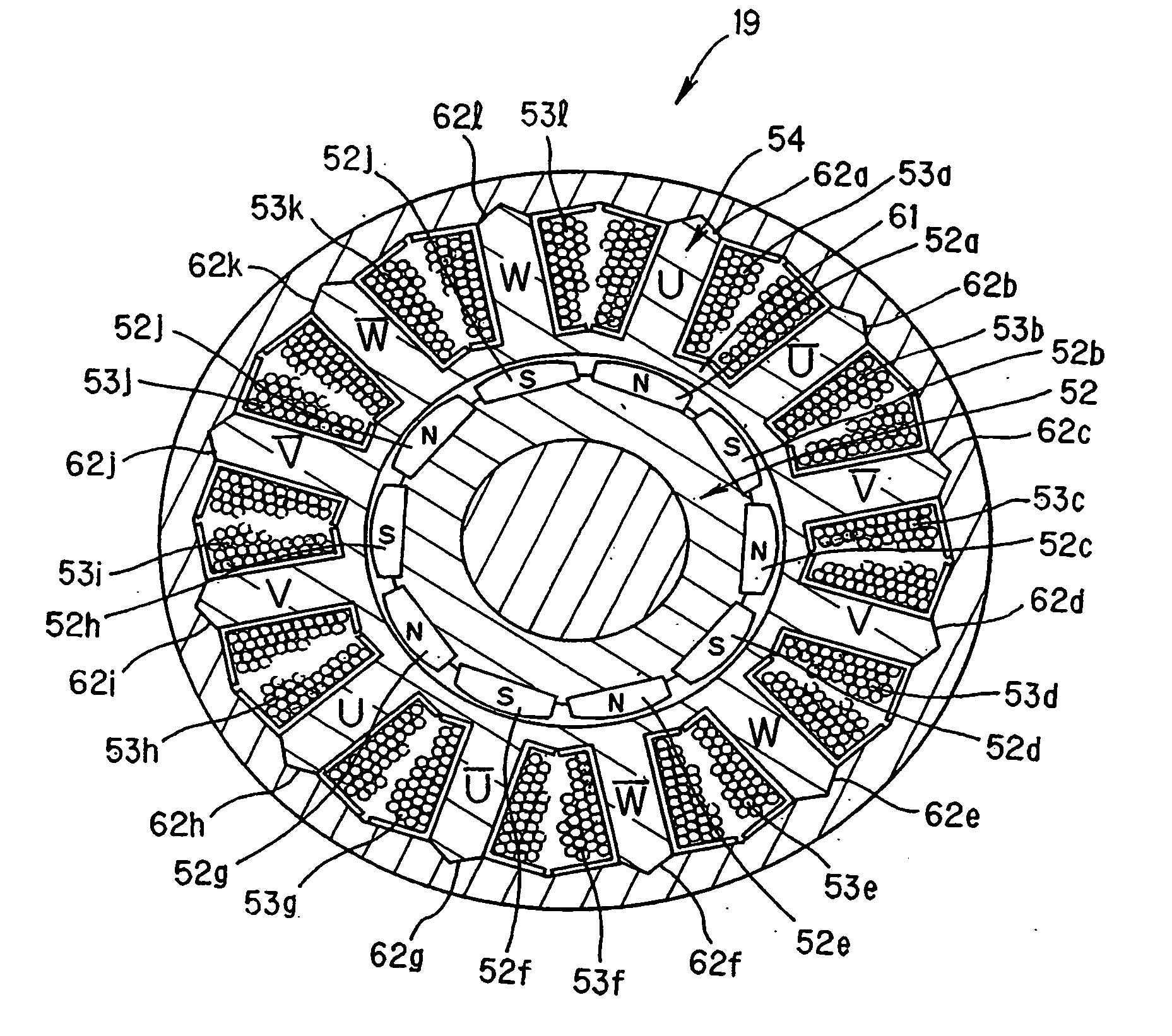
Embodiment Construction

[0034] It should be appreciated that various constructions, shapes, sizes, positions, etc. explained below in relation to various embodiments of the present invention are just for illustrative purposes, and that the present invention is not limited to the embodiments described below and may be modified variously without departing from the scope indicated by the appended claims.

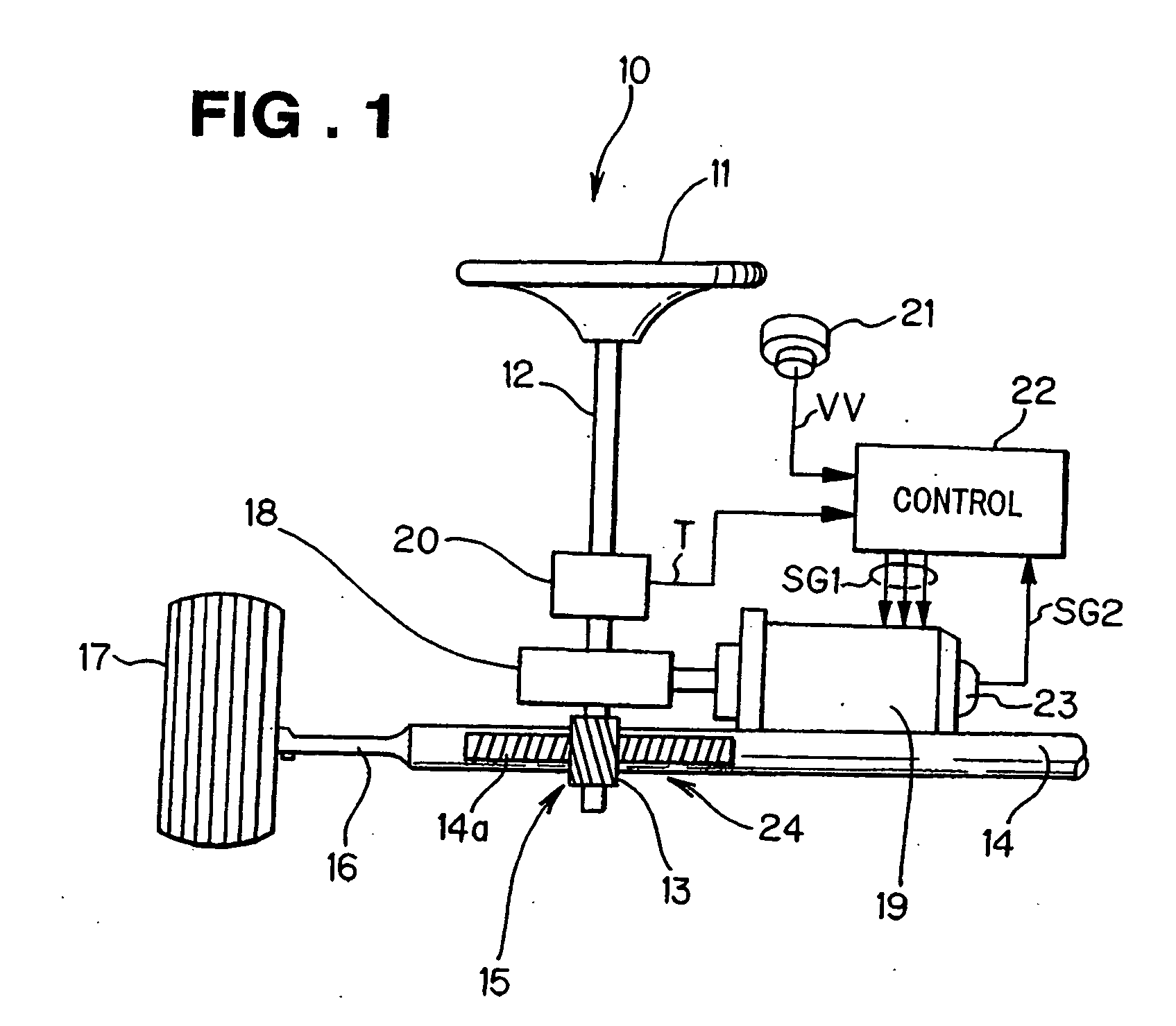
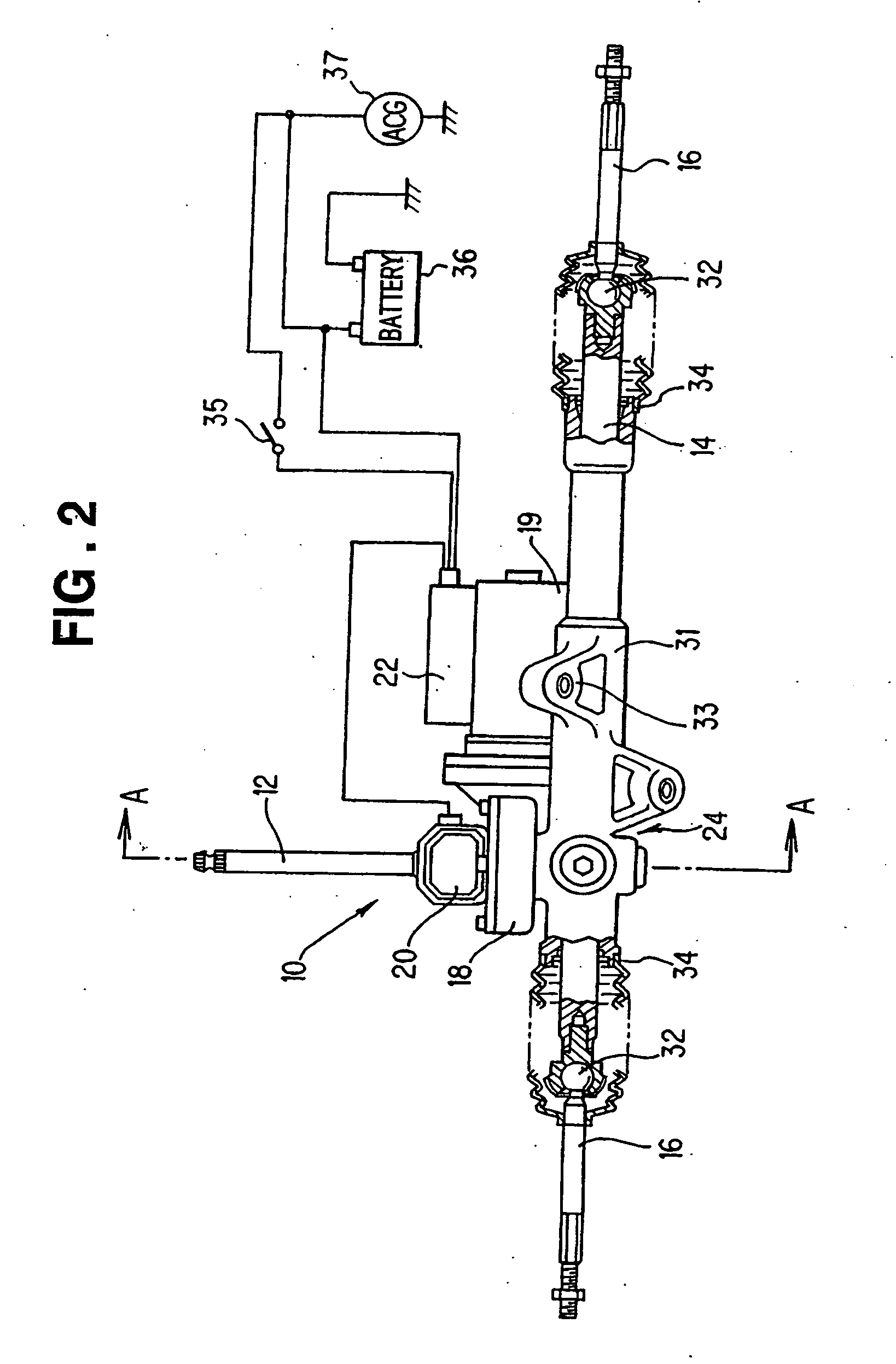
[0035] First, with reference to FIGS. 1 to 4, descriptions will be given about a general setup, specific mechanical and electrical arrangements and layout of electronic components of an electric power steering apparatus equipped with an electric motor of the present invention.

[0036]FIG. 1 is a view showing the general setup of the electric power steering apparatus 10, which is applied, for example, to a passenger vehicle. The electric power steering apparatus 10 is constructed to impart a steering assist force (steering assist torque) to a steering shaft 12 connected to a steering wheel 11 of the vehicle. Th...


PUM


Abstract

Coil windings are provided on each predetermined pair of adjoining tooth portions in a 8-like configuration by: winding a lead wire around one of the tooth portions a predetermined number of times, starting from a point adjacent to one side portion of a teeth-adjoining region; then winding the lead wire around the other tooth portion the same number of times, starting from a point adjacent to the other side portion of the teeth-adjoining region opposite from the one side portion; and terminating the winding of the lead wire at a point adjacent to the teeth-adjoining region.

Description

FIELD OF THE INVENTION[0001] The present invention relates to electric motors, electric power steering apparatus equipped with electric motors, and wire winding methods for electric motors. BACKGROUND OF THE INVENTION [0002] As well known, the electric power steering apparatus are steering assisting apparatus which are constructed to activate an electric motor (steering assisting motor) as a human driver manually operates a steering wheel during travel of a motor vehicle, to thereby assist the driver's manual steering effort. In such electric power steering apparatus, the steering assisting motor, which provides a steering assist force or torque, is controlled by a motor control section on the basis of a steering torque signal generated by a steering torque detection section detecting steering torque that is produced on the steering shaft by driver's operation of the steering wheel and a vehicle velocity signal generated by a vehicle velocity detection section detecting a traveling ...

Claims


Application Information

Patent Timeline
IPC IPC(8): B62D5/04H02K1/00H02K1/12H02K3/00H02K3/18H02K3/28H02K3/46H02K7/116H02K15/095H02K21/16
CPCH02K3/28H02K15/095H02K7/1166
Inventor AKUTSU, SHIGEMITSUATARASHI, HIROFUMIKURIBAYASHI, TAKASHIBABA, HIROYUKIFUKUDA, TAKEONAKAZUMI, MITSUO
Owner HONDA MOTOR CO LTD
Learn More