Plasma display apparatus

a technology of plasma display and display panel, which is applied in the direction of static indicating device, identification means, instruments, etc., can solve the problems of increasing the total the need to change the entire shape, and achieves the effect of enhancing the heat dissipation performance of the plasma display panel, reducing the overall weight of the plasma display apparatus, and facilitating coping

Inactive Publication Date: 2005-11-03
SAMSUNG SDI CO LTD
View PDF18 Cites 60 Cited by
  • Summary
  • Abstract
  • Description
  • Claims
  • Application Information

AI Technical Summary

Benefits of technology

[0027] As described above, in the plasma display apparatus according to the present invention, the frame and the boss plate are separated, the frame is made of metal to support the plasma display panel which is provided with a thermally conductive member, the boss plate is made of a material having a weight less than that of the frame, and is fitted with the driving circuit boards, and the a

Problems solved by technology

The chassis base can effectively perform heat dissipation of the plasma display panel and compensation for the rigidity of the plasma display panel because the chassis base is made of metal having excellent thermal conductivity, but it has a problem in that the total weight of the plasma display apparatus is increased
Since the chassis base

Method used


Image

  • Plasma display apparatus
  • Plasma display apparatus
  • Plasma display apparatus

Examples


first embodiment

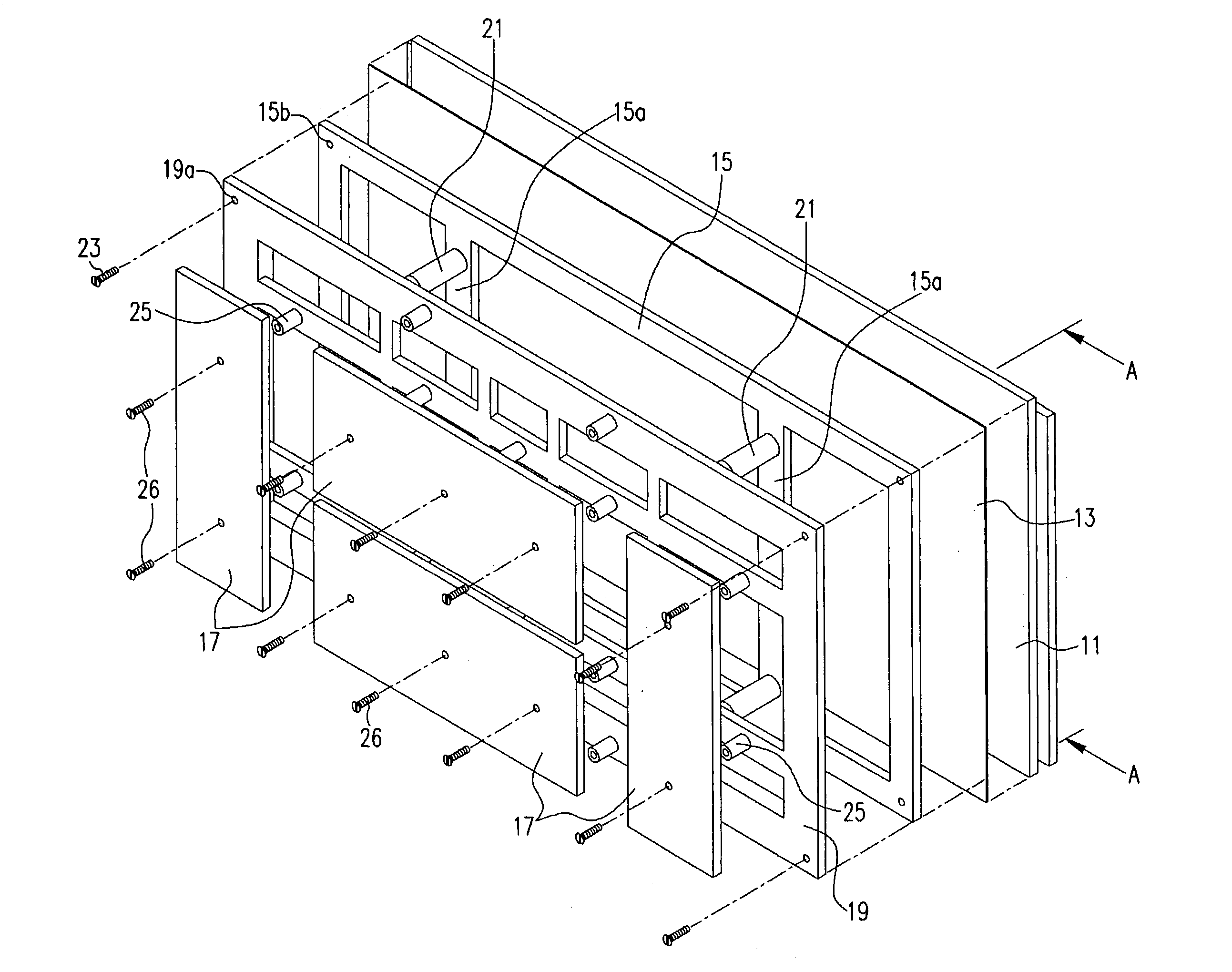
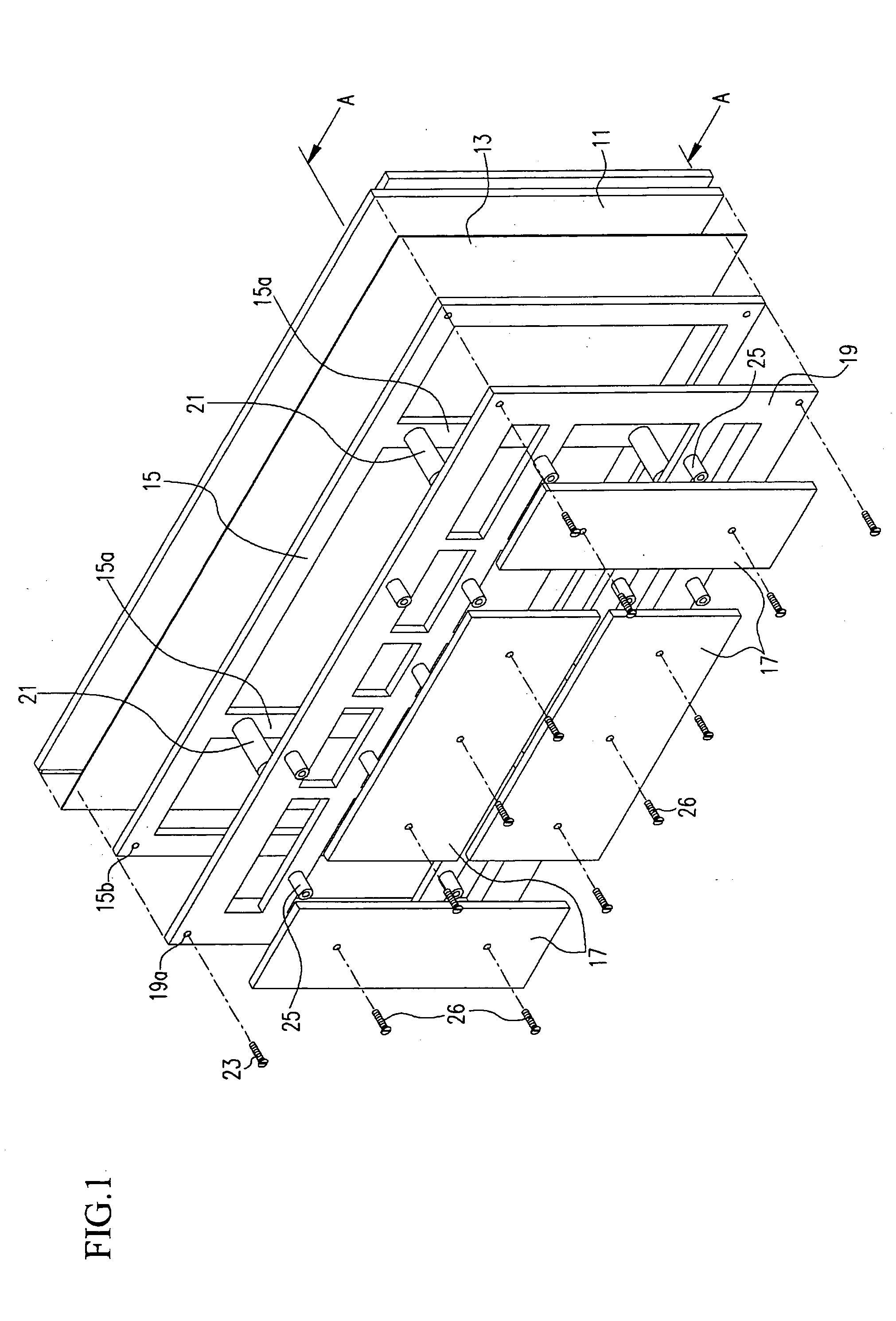
[0041]FIG. 1 is an exploded perspective view schematically illustrating a plasma display apparatus according to the present invention.

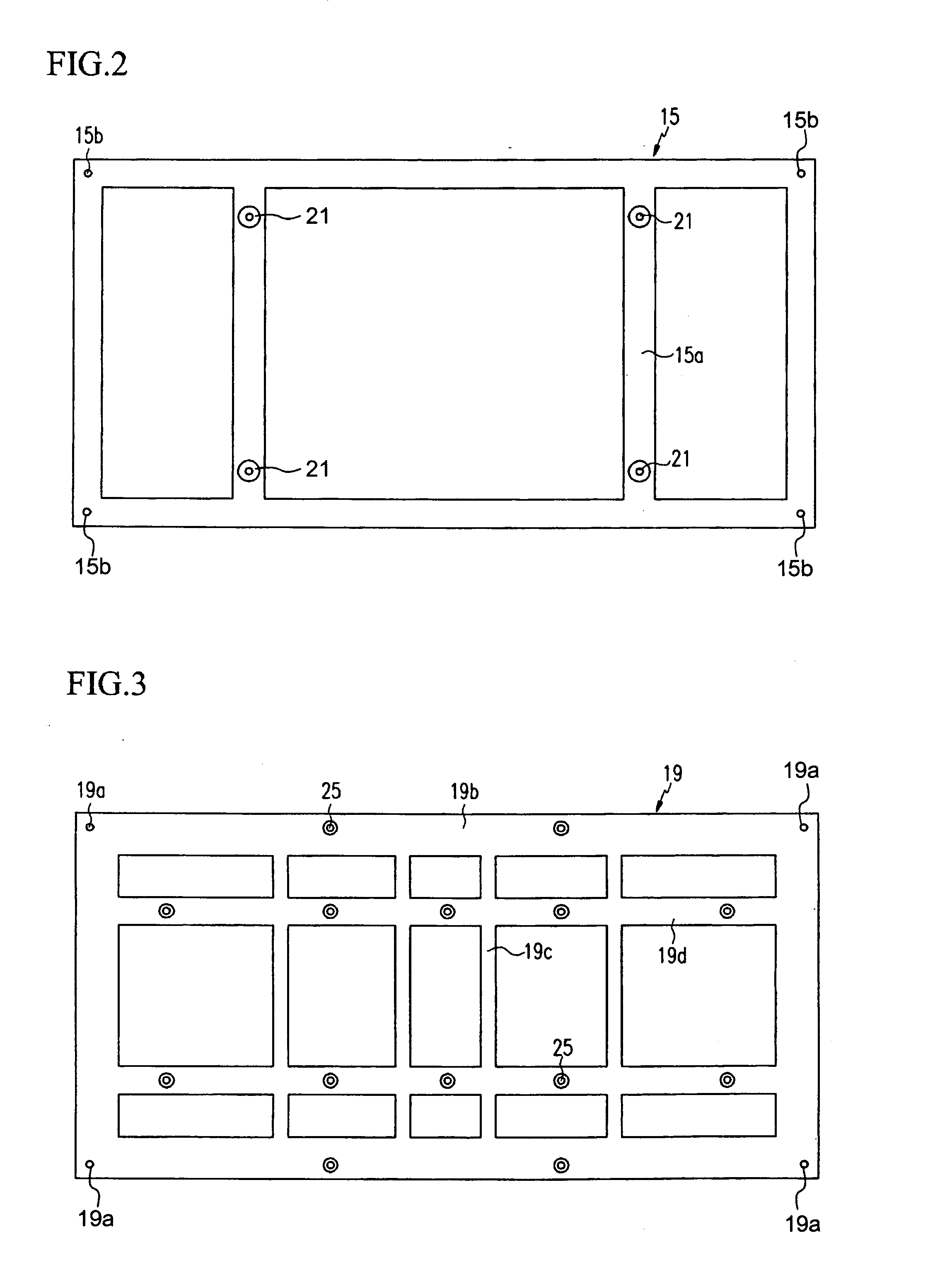
[0042] Referring to FIG. 1, the plasma display apparatus comprises a plasma display panel 11 for displaying images using gas discharge, a thermally conductive member 13 which is provided on the rear surface of the plasma display panel 11, and which dissipates heat generated by the plasma display panel 11, a frame 15 supporting the plasma display panel 11, and a boss plate 19 which is fixed to the rear surface of the frame 15, and to which driving circuit boards 17 are fitted and by which driving circuit boards 17 are supported.

[0043] Since the plasma display panel 11 has a construction for displaying images using gas discharge, and since the present invention is directed toward a coupling structure between the plasma display panel 11 and other constituent elements, specific description of the plasma display panel 11 will be omitted.

[0044] The therma...

second embodiment

[0060]FIG. 6 is an exploded perspective view schematically illustrating a plasma display apparatus according to the present invention.

[0061] Referring to FIG. 6, the plasma display apparatus comprises a plasma display panel 11 for displaying images using gas discharge, a thermally conductive member 13 which is formed on the rear surface of the plasma display panel 11, and which dissipates heat generated from the plasma display panel 11, a frame 35 to which the plasma display panel 11 is fitted and by which the plasma display panel 11 is supported, and a boss plate 41 which is fixed to the rear side of the frame 35, and which supports driving circuit boards 37 and set circuit boards 39 fitted thereto.

[0062]FIG. 7 is a diagram of the rear side of the frame of the plasma display apparatus according to the second embodiment of the present invention.

[0063] Referring to FIG. 7, the frame 35 is attached to the rear surface of the plasma display panel 11, and is made of a material capable...

third embodiment

[0078]FIG. 11 is a perspective view of a boss plate of a plasma display apparatus according to the present invention.

[0079] As shown in FIG. 11, when the boss plate 61 is bent, the fitting of the set circuit boards 39, manufactured by the set makers, to the boss plate 61 can be easily carried out, and mechanical interference between the boss plate 61 and the set circuit boards 39 can be prevented, and the plasma display apparatus can be made with a thickness which is further reduced.


PUM


Abstract

A plasma display apparatus is capable of enhancing the heat dissipating ability of a plasma display panel, and of reducing the total weight of the plasma display apparatus. The plasma display apparatus comprises a plasma display panel, a frame to which the plasma display panel is attached and by which the plasma display panel is supported, and a boss plate fixed to a rear surface of the frame and fitted with driving circuit boards. The frame is formed in the shape of a rectangular frame which contacts edges of the plasma display panel. A vertical member is vertically disposed in the rectangular frame. The vertical member has wall-mounted bosses which support the total weight of the plasma display apparatus. Other features include a thermally conductive member formed on the rear surface of the frame, and formation of an air passage between the thermally conductive member and the driving circuit boards.

Description

CLAIM OF PRIORITY [0001] This application makes reference to, incorporates the same herein, and claims all benefits accruing under 35 U.S.C. 119 from two applications for PLASMA DISPLAY APPARATUS both of which were earlier filed in the Korean Intellectual Property Office on 29 Apr. 2004 and, there duly assigned Serial Nos. 10-2004-0029933 and 10-2004-0029934, respectively. BACKGROUND OF THE INVENTION [0002] 1. Technical Field [0003] The present invention relates to a plasma display apparatus and, more particularly, to a plasma display apparatus in which a plasma display panel (PDP) is supported by a thermally conductive member, a frame, and a boss plate. [0004] 2. Related Art [0005] As is known well, a plasma display apparatus comprises a plasma display panel for generating plasma through gas discharge and for displaying images using the plasma, a chassis base supporting the plasma display panel, and driving circuit boards which are provided at the side of the chassis base opposite ...

Claims


Application Information

Patent Timeline
IPC IPC(8): H01J17/28G09F9/00G09G5/00H01J11/44H05K7/00H05K7/20
CPCH05K7/20963H01J2217/492
Inventor BAE, SUNG-WONJUNG, NAM-SUNG
Owner SAMSUNG SDI CO LTD
Why Eureka
Try Eureka