Liquid sensor and liquid container including the sensor

a liquid sensor and liquid container technology, applied in the direction of level indicators, instruments, printing, etc., can solve the problems of limited detection range, complicated seal structure of the electrode, and inability to detect the kind of ink available, so as to prevent the generation of unnecessary vibration, and reliably decide the presence of liquid

Active Publication Date: 2005-11-03
SEIKO EPSON CORP
View PDF7 Cites 59 Cited by
  • Summary
  • Abstract
  • Description
  • Claims
  • Application Information

AI Technical Summary

Benefits of technology

[0020] Another object of the present invention is to provide a liquid sensor which prevents air bubbles from staying in a cavity, and can certainly judge the existence of liquid, and a liquid container including the sensor.
[0021] Another object of the present invention is to provide a liquid sensor which prevents ink from remaining in a cavity, and can certainly judge the existence of liquid, and a liquid container including the sensor.
[0022] It is a further object of the invention to provide a liquid sensor employing a suitable cavity shape for preventing air bubbles from staying and ink from remaining in a cavity and capable of preventing the generation of an unnecessary vibration in the residual vibration of a vibration portion to reliably decide the presence of a liquid, and a liquid container comprising the sensor.
[0023] It is a further object of the invention to provide a liquid sensor employing a suitable cavity shape capable of preventing air bubbles from staying and ink from remaining in the cavity to reliably decide the presence of a liquid by providing a liquid supply port and a liquid discharge port in corresponding positions to both ends in the longitudinal direction of the cavity.

Problems solved by technology

However, in the method in which the number of discharges of ink droplets and the amount of ink are accumulated by the software and the ink consumption is managed by calculation, there is a problem as described below.
Although the variations in the weight of ink droplets do not have an influence on the picture quality, in view of a case where an error in the amount of ink consumption due to the variations is accumulated, ink whose amount includes a margin is filled in the ink cartridge.
Accordingly, there arises a problem that the ink corresponding to the margin remains according to an individual.
However, since the detection of the liquid surface of ink depends on the conductivity of the ink, there are defects that the kind of detectable ink is limited, and the seal structure of the electrode becomes complicated.
Besides, since a noble metal having superior conductivity and high corrosion resistance is generally used as a material of the electrode, the manufacturing cost of the ink cartridge runs up.
Further, since two electrodes are required to be mounted, the manufacturing steps are increased, and as a result, the manufacturing cost runs up.
As a result, there is a problem in that it is hard to reliably decide the presence of an ink.
It can be supposed that such an unnecessary vibration is generated because a difference in a vibration mode is great between a forcible vibration generated in the vibration portion when the driving pulse is applied to the piezoelectric unit and the residual vibration (free vibration) generated in the vibration portion after the forcible vibration.

Method used


Image

  • Liquid sensor and liquid container including the sensor
  • Liquid sensor and liquid container including the sensor
  • Liquid sensor and liquid container including the sensor

Examples


Embodiment Construction

[0239] Hereinafter, a liquid sensor according to an embodiment of the invention and an ink cartridge (liquid container) including the liquid sensor will be described with reference to the drawings.

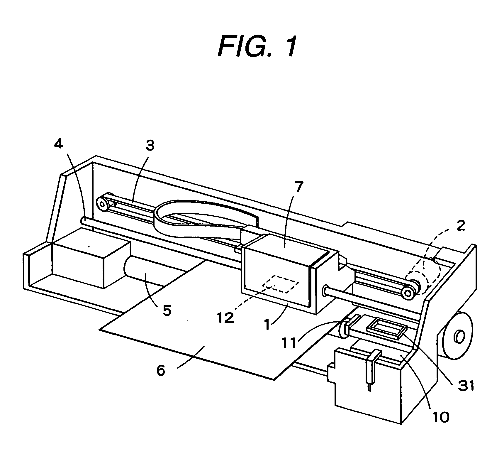
[0240]FIG. 1 shows a schematic structure showing an example of an ink jet recording apparatus (liquid jetting apparatus) in which an ink cartridge according to the present invention can be used. In FIG. 1, reference numeral 1 denotes a carriage, and the carriage 1 is constructed to be guided by a guide member 4 and to be reciprocated in an axial direction of a platen 5 through a timing belt 3 driven by a carriage motor 2.

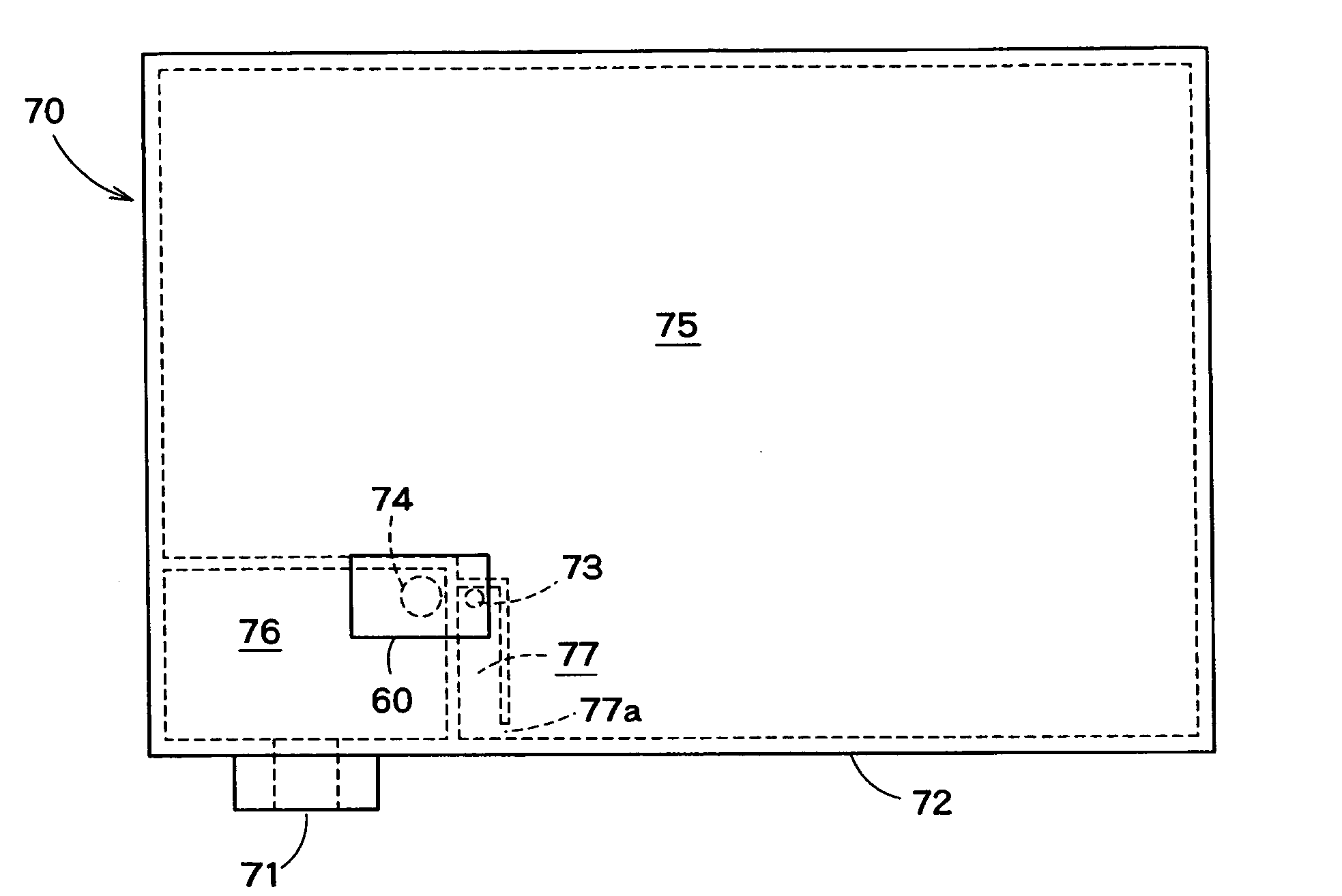
[0241] An ink jet recording head 12 is mounted to a side of the carriage 1 opposite to a recording sheet 6, and an ink cartridge 7 for supplying ink to the recording head 12 is detachably mounted on an upper part thereof.

[0242] A cap member 31 is disposed at a home position (in the drawing, right side) as a non-printing region of the recording apparatus, and the cap mem...


PUM


Abstract

The invention relates to a liquid sensor which can certainly judge the existence of liquid, and a liquid container including the sensor. A liquid sensor 60 in which a piezoelectric element having a piezoelectric layer 47 on both surfaces of which electrodes 46 and 49 are formed is used, and a bottom 43a of a cavity 43 for receiving liquid as a detection object is vibrated. The sensor 60 includes a vibration cavity forming base portion 40 in which the cavity 43 having the vibratable bottom 43a is formed, and a flow path forming base portion 50 laminated on the vibration cavity forming base portion 40. A liquid supply path 53 for supplying the liquid as the detection object to the cavity 43 and a liquid discharge path 54 for discharging the liquid as the detection object from the cavity 43 are formed in the flow path forming base portion 50.

Description

TECHNICAL FIELD [0001] The present invention relates to a liquid sensor and a liquid container including the sensor, and particularly to a liquid sensor suitable for the detection of the residual amount of liquid in a liquid jetting apparatus and a liquid container including the sensor. BACKGROUND ART [0002] As a typical example of a conventional liquid jetting apparatus, there is an ink jet recording apparatus including an ink jet recording head for image recording. As other liquid jetting apparatuses, there are enumerated, for example, an apparatus including a color material jetting head used for color filter manufacture of a liquid crystal display or the like, an apparatus including an electrode material (conductive paste) jetting head used for electrode formation of an organic EL display, a surface emission display (FED) or the like, an apparatus including a living organic material jetting head used for biochip manufacture, an apparatus including a sample jetting head as a preci...

Claims


Application Information

Patent Timeline
Patent Type & Authority Applications(United States)
IPC IPC(8): B41J2/175
CPCB41J2/17566B41J2/17509B41J2/17553G01F23/296B41J2/16523G01F23/2966
Inventor TAKAHASHI, TOMOAKIZHANG, JUNHUA
Owner SEIKO EPSON CORP
Why Eureka
Try Eureka