Systems and methods for monitoring and controlling remote devices

a remote device and system technology, applied in the field of remote system monitoring, control and reporting, can solve the problems of prohibitive control system cost, local controller installation and operation expenses, and inability to monitor and control prior art control systems, etc., and achieve the effect of integration into pre-existing systems

Inactive Publication Date: 2005-11-03
HUNT TECH INC +1
View PDF99 Cites 210 Cited by
  • Summary
  • Abstract
  • Description
  • Claims
  • Application Information

AI Technical Summary

Benefits of technology

[0010] To successfully communicate between the transceiver(s) and the gateway interface, a preferred embodiment of the present invention can receive a plurality of RF signal transmissions containing a packet protocol via a preferred embodiment of data structures that include sender and receiver identifiers, a description of the packet itself, a message number, commands, data, and an error detector. The data structure can be integrated with alternate data communication protocols for use with many other communication systems and networks. Also, a preferred embodiment of the present invention can be integrated into an existing control system using networked wireless transceivers. Distinct control signals from the pre-existing system can be mapped into the packet protocol enabling integration into a pre-existing control system easily and inexpensively.

Problems solved by technology

A problem with expanding the use of control system technology is the cost of the sensor / actuator infrastructure required to monitor and control such systems.
Another prohibitive cost of control systems is the installation and operational expenses associated with the local controller.
As a result, prior art control systems often are susceptible to a single point of failure if the local controller 110 goes out of service.
Also, appropriately wiring an existing industrial plant can be dangerous and expensive.

Method used


Image

  • Systems and methods for monitoring and controlling remote devices
  • Systems and methods for monitoring and controlling remote devices
  • Systems and methods for monitoring and controlling remote devices

Examples


Embodiment Construction

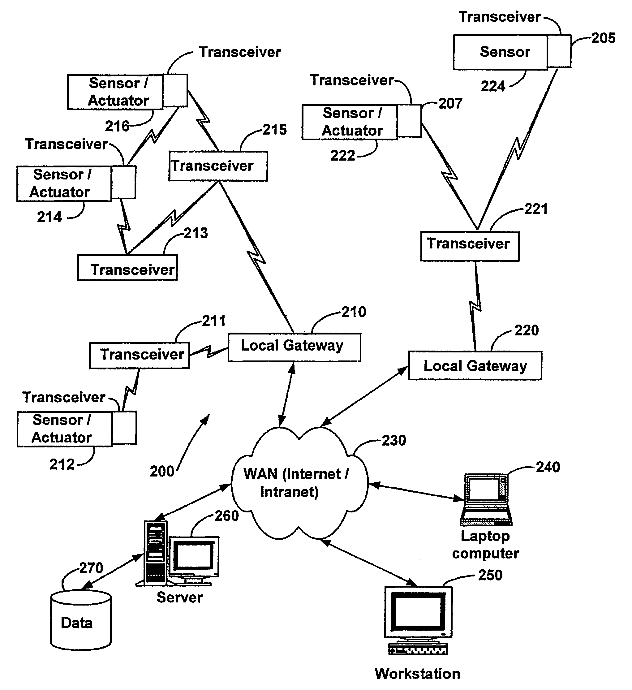
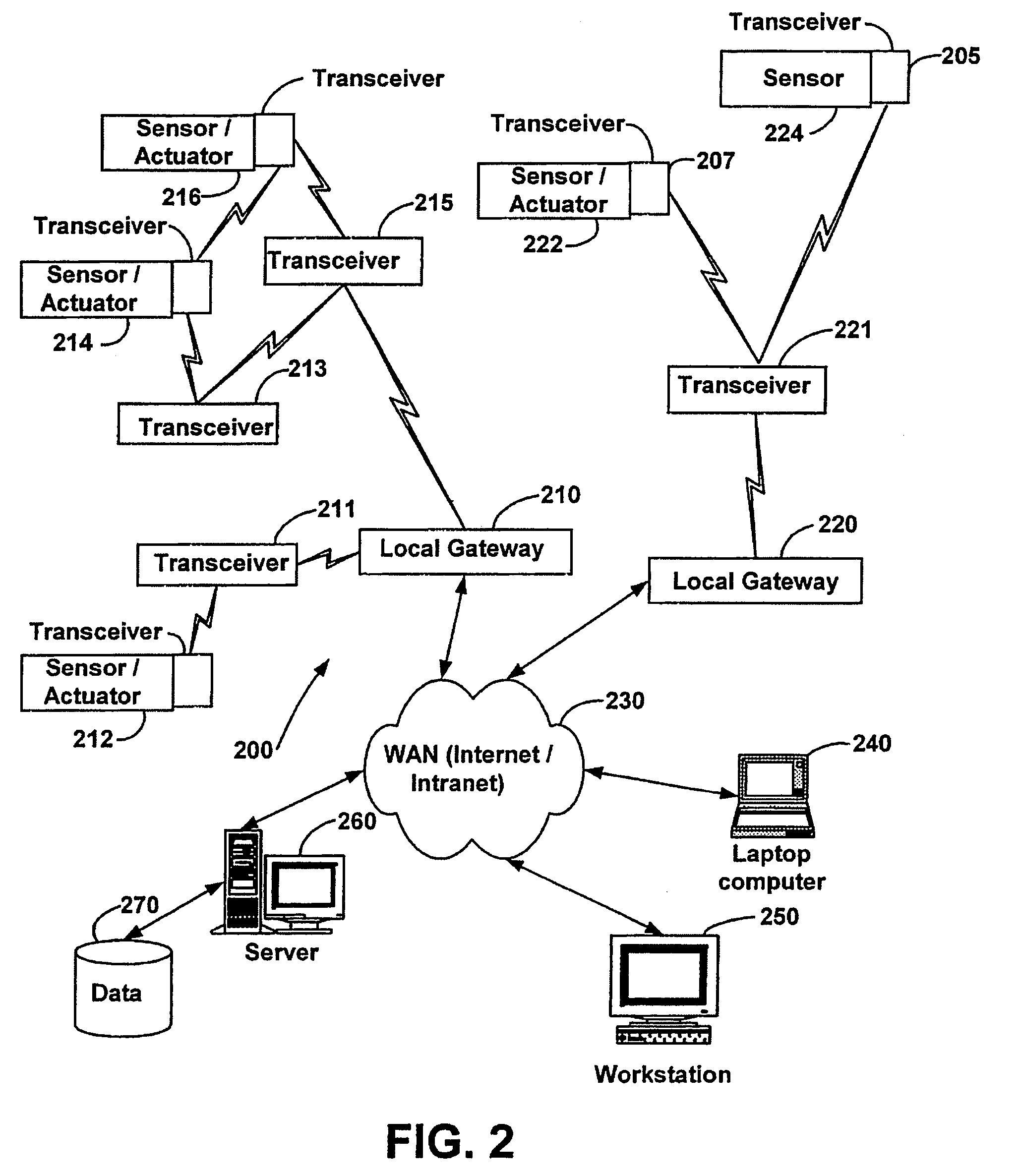
[0020]FIG. 2 sets forth a block diagram illustrating a preferred embodiment of a control system 200 in accordance with the present invention. The control system 200 can consist of one or more transceivers. An exemplary transceiver 205 can be integrated with a sensor 224 to form a first combination. A second transceiver 207 can be integrated with an actuator 222 to form a second combination. The transceivers 205, 207 are preferably wireless RF transceivers that are small and transmit a low-power-RF signal. As a result, in some applications, the transmission range of a given transceiver 205, 207 may be limited. As will be appreciated from the description that follows, this limited transmission range of the transceivers 205, 207 can be a desirable characteristic of the control system 200. Although the transceivers 205, 207 are depicted without user interfaces such as a keypad (not shown), the transceivers 205, 207 may be configured with user selectable buttons or an alphanumeric keypad...


PUM


Abstract

Systems and methods for monitoring and controlling remote devices are provided. In an embodiment, a system can comprise one or more remotely controlled sensors and actuators. The remote sensors / actuators can interface with uniquely identified remote transceivers that transmit and / or receive data. The embodiment can also comprise a plurality of transceivers each having a unique address, and a controller adapted to communicate with at least one of the transceivers in a preformatted message. A sensor can be associated with at least one transceiver to detect a condition and output a data signal to the transceiver, and an actuator can be associated with a transceiver to receive a control signal and activate a device. Other embodiments are also claimed and described.

Description

CROSS-REFERENCE TO RELATED APPLICATIONS [0001] This application is a continuation of U.S. patent application Ser. No. 09 / 812,044, filed Mar. 19, 2001, and entitled “System and Method for Monitoring and Controlling Remote Devices”, now U.S. Pat. No. ______. U.S. patent application Ser. No. 09 / 812,044 is a continuation-in-part of: U.S. patent application Ser. No. 09 / 704,150, filed Nov. 1, 2000, and entitled “System and Method for Monitoring and Controlling Residential Devices”, now U.S. Pat. No. 6,891,838; U.S. patent application Ser. No. 09 / 271,517, filed Mar. 18, 1999, and entitled, “System For Monitoring Conditions in a Residential Living Community”, now abandoned; U.S. patent application Ser. No. 09 / 439,059, filed Nov. 12, 1999, and entitled, “System and Method for Monitoring and Controlling Remote Devices”, now U.S. Pat. No. 6,437,692; U.S. patent application Ser. No. 09 / 102,178, filed Jun. 22, 1998, and entitled, “Multi-Function General Purpose Transceiver”, now U.S. Pat. No. 6,...

Claims


Application Information

Patent Timeline
Patent Type & Authority Applications(United States)
IPC IPC(8): G01V1/36G05B1/00G05B23/02G05D1/00G08B25/00H04B7/00H04J3/16H04J3/22H04J3/24H04L12/28H04L12/56H04L29/08
CPCG01V1/364G05B19/4183H04L67/125G08B25/007G08B25/009G05B2219/31093Y04S40/18H04W4/14Y02P90/02G08B21/18G08B27/005H04B7/15
Inventor PETITE, THOMAS DAVID
Owner HUNT TECH INC
Why Eureka
Try Eureka