Adaptive de-blocking filtering apparatus and method for MPEG video decoder

a filtering apparatus and video decoder technology, applied in the field of postprocessing of blockbased coded video, can solve the problems of difficult to reduce the blocking artifact with a small operation capacity, noticeable blocking artifacts, and serious problems of moving picture compression, and achieve the effect of low computational complexity

Active Publication Date: 2005-11-03
MEDIATEK INC
View PDF39 Cites 110 Cited by
  • Summary
  • Abstract
  • Description
  • Claims
  • Application Information

AI Technical Summary

Benefits of technology

[0028] One objective of the claimed invention is therefore to provide a highly adaptive de-blocking filter for an MPEG video decoder that can be used for both frame-coded and field-coded pictures at a wide range of bit rates with low computational complexity, to solve the above-mentioned problems.

Problems solved by technology

However, this individual processing causes blocking artifacts that are noticeable at boundaries between blocks.
At low coding bit rates, blocking artifacts are a serious problem for moving picture compression.
Since a real-time operation is necessary in coding and decoding a moving picture, it is difficult to reduce the blocking artifact with a small operation capacity.
As such, existing video compression algorithms and standards continue to have unwanted visual artifacts appear when the original information is compressed with loss, and these unwanted visual artifacts become more visible when the coding bit rates become lower.
In this case, coarse quantization of the transform coefficients causes discontinuities at the block boundaries.
However, this method of changing the processes of coding and decoding increases the amount of bits to be transmitted.
Additionally, such an approach is unacceptable in many situations because the resulting data stream no longer complies with the applicable standards.
The main drawback of these iterative de-blocking methods is their high computational complexity, which prevents them from being used in a real-time video decoder.
The de-blocking method proposed by Kim et al. results in high subjective quality of decoded images at low bit rates; however, it smoothes real edges and severely degrades the objective quality at higher bit rates due to the strong low-pass filter used in the smooth region mode.
Moreover, this method does not consider block artifacts in inter-coded MBs that are caused by the motion compensated prediction.
However, due to its highly adaptive nature, this method also has a very high computational complexity.

Method used


Image

  • Adaptive de-blocking filtering apparatus and method for MPEG video decoder
  • Adaptive de-blocking filtering apparatus and method for MPEG video decoder
  • Adaptive de-blocking filtering apparatus and method for MPEG video decoder

Examples


Embodiment Construction

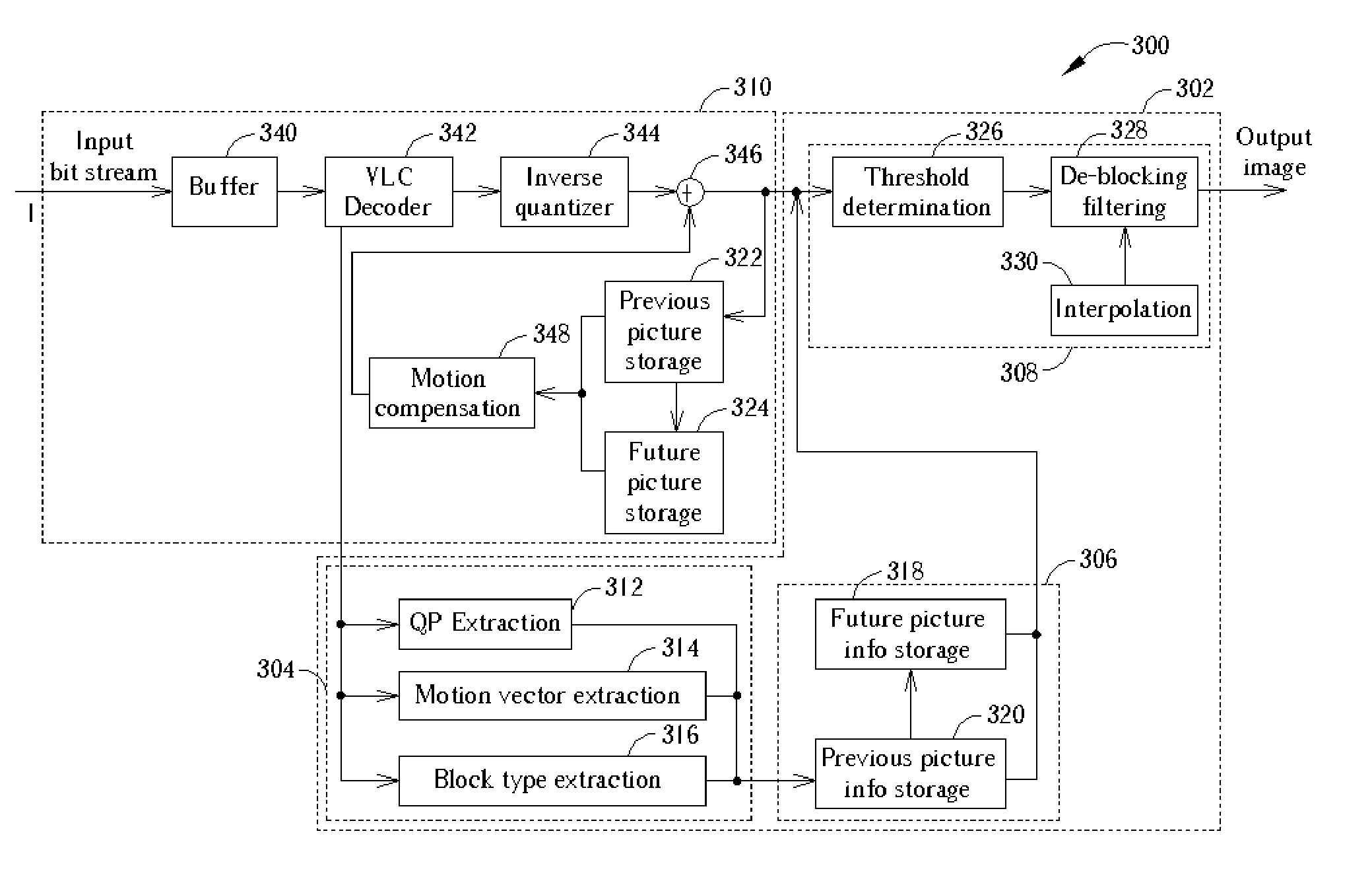
[0068]FIG. 3 is a block diagram showing a video decoder 300 incorporating a post-processing de-blocking device 302 according to the present invention. As described previously, when the de-blocking filter is integrated into a video decoder 300 as a post-processing de-blocking device 302, the post-processing de-blocking device 302 operates on decoded frames after the decoding loop. In the block diagram shown in FIG. 1, the post-processing de-blocking device 302 comprises three units: a picture-information extraction and buffering unit 304, a picture-information reordering unit 306, and a post-processing unit 308. The post-processing unit 308 is cascaded with a standard MPEG decoder 310 without changing the bit stream syntax of an input bit stream 1. The standard MPEG decoder 310 receives the input bit stream I and includes a buffer 340, a variable length code (VLC) decoder 342, an inverse quantizer 344, a summing unit 346, a motion compensation unit 348, previous picture storage 322, ...


PUM


Abstract

A post processing de-blocking filter includes a threshold determination unit for adaptively determining a plurality of threshold values according to at least differences in quantization parameters QPs of a plurality of adjacent blocks in a received video stream and to a user defined offset (UDO) allowing the threshold levels to be adjusted according to the UDO value; an interpolation unit for performing an interpolation operation to estimate pixel values in an interlaced field if the video stream comprises interlaced video; and a de-blocking filtering unit for determining a filtering range specifying a maximum number of pixels to filter around a block boundary between the adjacent blocks, determining a region mode according to local activity around the block boundary, selecting one of a plurality of at least three filters, and filtering a plurality of pixels around the block boundary according to the filtering range, the region mode, and the selected filter.

Description

BACKGROUND OF INVENTION [0001] 1. Field of the Invention [0002] The present invention generally relates to post-processing of block-based coded video, and more particularly to a filtering method and apparatus for removing blocking artifacts from MPEG-coded video. [0003] 2. Description of the Prior Art [0004] A wide range of new applications in visual communications have been made possible due to the rapidly evolving telecommunication and computer industries. Almost all the related applications, including video conferencing, mobile or PSTN video telephony, video over the Internet, and digital TV broadcasting, require very efficient data compression methods to fit a large amount of visual information into the narrow bandwidth of communication channels while preserving acceptable quality of the reconstructed data. [0005] To efficiently compress a time variable video sequence, redundancy in the temporal domain as well as in the two dimensional spatial domain must be reduced. The Moving ...

Claims


Application Information

Patent Timeline
Patent Type & Authority Applications(United States)
IPC IPC(8): H04N7/12H04N7/26H04N7/50
CPCH04N19/139H04N19/159H04N19/176H04N19/86H04N19/117H04N19/14H04N19/16H04N19/61
Inventor KWON, DO-KYOUNGSHEN, MEI-YINKUO, CHUNG-CHIEH
Owner MEDIATEK INC
Why Eureka
Try Eureka