Optical switch and optical branch/insertion unit comprising it

a technology of optical switch and optical branch, applied in the field of optical switch, can solve the problems of optical switch using prisms or reflectors, the loss of light at the time of reflection is inevitable, and the error rate of optical communication becomes high

Inactive Publication Date: 2005-11-03
HOYA CORP
View PDF19 Cites 6 Cited by
  • Summary
  • Abstract
  • Description
  • Claims
  • Application Information

AI Technical Summary

Problems solved by technology

However, the aforementioned optical switches using the prisms or the reflector had problems described below.
Conventional optical switches use a catoptric system, and a loss of lights at the time of reflection is inevitable when drop of the signal lights to the repeater station and addition of the signal light from the repeater station are conducted.
When such a PDL occurs, a bit error rate in the optical...

Method used


Image

  • Optical switch and optical branch/insertion unit comprising it
  • Optical switch and optical branch/insertion unit comprising it
  • Optical switch and optical branch/insertion unit comprising it

Examples


Embodiment Construction

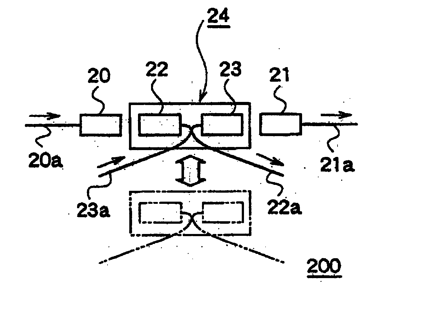
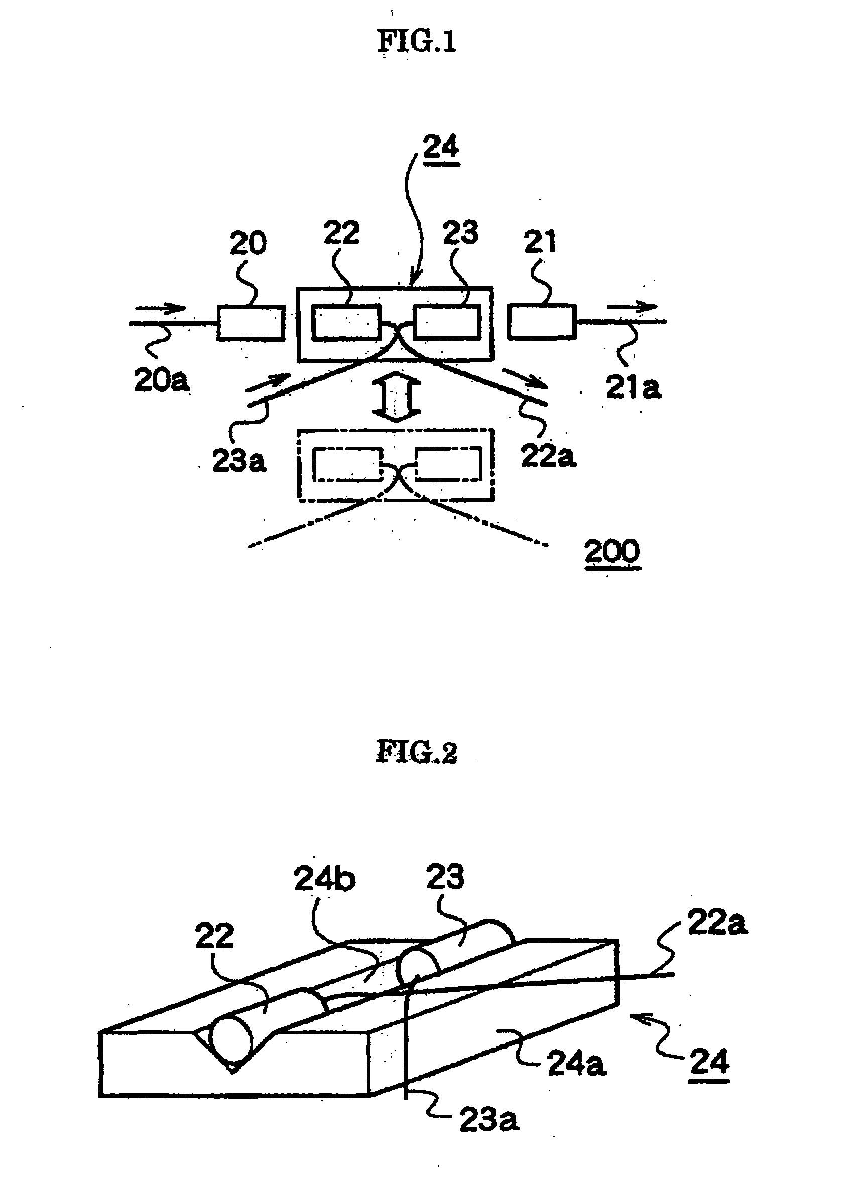
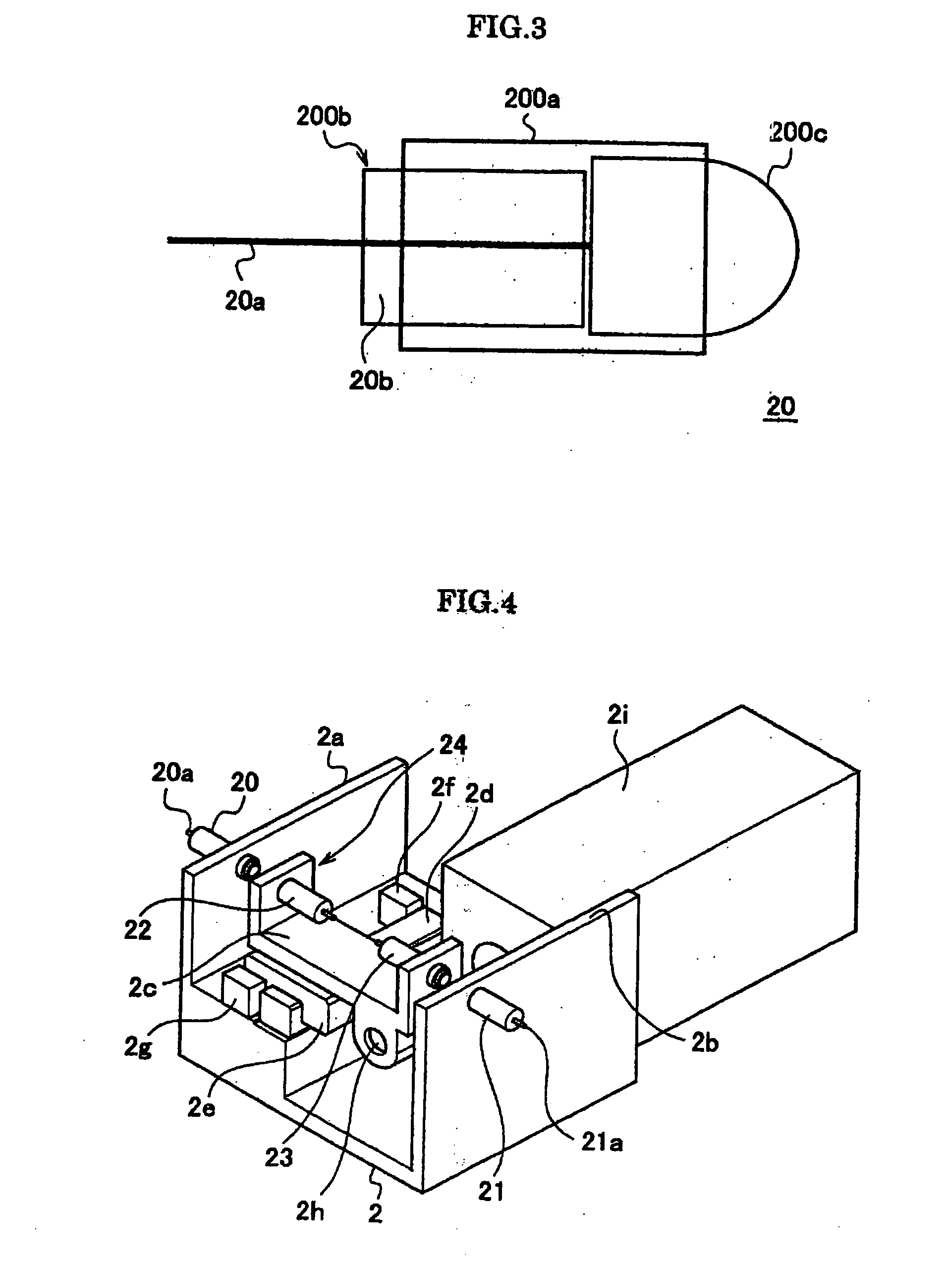
[0062]FIG. 1 is a plan view showing a structure of an optical switch 200 according to the present embodiment; FIG. 2 is a perspective view showing an example of an optical switching portion 24; FIG. 3 is a view showing a concrete structure of an input light outputting collimator device 20; FIG. 4 is a perspective view showing a concrete structure of an optical switch according to an embodiment of the present invention; FIG. 5 is a plan view showing a concrete structure of the optical switch according to the embodiment of the present invention; FIG. 6 is a perspective view showing a transformed example of the optical switch shown in FIG. 5; FIG. 7 is a perspective view showing another concrete structure of the optical switch according to the embodiment of the present invention; FIG. 8 is a plan view of the optical switch shown in FIG. 7; FIG. 9 and FIG. 10 are explanatory views of the optical switch shown in FIG. 7 and FIG. 8; and FIG. 11 is a view showing a structure of an optical a...


PUM


Abstract

An optical switch easy to adjust optical parts without using a catoptric system and an optical add/drop multiplexer using the optical switch are provided. Between an input light outputting collimator device 20 and an output light inputting collimator device 21 provided to face each other at a predetermined spaced interval, a drop light inputting collimator device 22 and an add light outputting collimator device 23 fixed and held on a movable holding member 24a in common are moved forward and retreated, and thereby a switching is conducted.

Description

TECHNICAL FIELD [0001] The present invention relates to an optical switch used for change of an optical path of a signal light or the like and an optical add / drop multiplexer using the optical switch in a field of optical communication or the like. BACKGROUND ART [0002] In recent years, a development of a wavelength-division multiplexing system has been advancing in an optical communication, and recently, an optical communication system has been drawing attention, which has an add / drop (Add / Drop Multiplexer: ADM) function to sort out and utilize only a signal light of a specific wavelength from among plural signal lights at a repeater station being provided in a middle of an optical transmission line, or to add and transmit other signals from this repeater station into the optical transmission line, in addition to perform a transmission / reception between two stations. A device disclosed in Japanese Patent Laid-open No. 2000-183816 is known as an optical add / drop multiplexer utilized...

Claims


Application Information

Patent Timeline
IPC IPC(8): G02B6/26G02B6/35
CPCG02B6/3508G02B6/356G02B6/3592G02B6/3572G02B6/358G02B6/3564
Inventor KAGAMI, KAORUASAI, HIDEKUNIYOKOO, YOSHIATSU
Owner HOYA CORP
Why Eureka
Try Eureka