
System and method for detecting a fault in a multiple receiver system

a multiple receiver and fault technology, applied in the direction of receiver monitoring, transmission monitoring, instruments, etc., can solve the problems of faulty voice and/or data communication, poor calibration or hardware malfunction, and the receiver in the multiple receiver system occasionally suffers from faults, so as to save hardware costs and the associated costs of deployment and calibration

Active Publication Date: 2005-11-03
WSOU INVESTMENTS LLC
View PDF8 Cites 12 Cited by
  • Summary
  • Abstract
  • Description
  • Claims
  • Application Information

AI Technical Summary

Benefits of technology

[0007] Advantages of the method and system for detecting a fault in a multiple receiver system of the present invention are that only one radio system with multiple receivers may be needed to detect a fault. This helps save hardware costs as well as deployment and calibration costs associated with hardware. Furthermore no extra energy may be needed to generate a extra pilot signal that is used only for fault detection. In addition, with the present invention, a fault in a particular receiver system of a multiple receiver system may be determined. Moreover, a software embodiment of the invention may allow flexibility to react to different scenarios and to upgrade the fault detector process when desired.

Problems solved by technology

Receivers in a multiple receiver system occasionally suffer from faults such as poor calibration or hardware malfunction.
If the fault goes uncorrected, then information may not be properly received by the multiple receiver system causing faulty voice and / or data communications.
If a significant power difference exists between the pilot signal transmit power of the first radio system and the output power of the second radio system receiver as a result of the pilot signal, a fault is determined to exist in the second radio system.
Problems with this approach for detecting a fault are that two radio systems are needed, one for transmitting a pilot signal and one for receiving the pilot signal.
Furthermore, it may be difficult to determine which receiver system is faulty where there is more than one receiver system in the second radio system.
If a significant difference in power exists between the output of the first radio system pilot signal and the output of the first radio system receiver, a fault is determined to exist in the first radio system.
Problems associated with this approach are that extra energy may be needed to generate the extra pilot signal only for fault detection purposes.
Additionally, it may be difficult to determine which receiver system is faulty where there is more than one receiver system in the first radio system.
A problem with this approach is that it may be difficult to determine which receiver system is faulty where there is more than one receiver system in the first radio system.

Method used


Image

  • System and method for detecting a fault in a multiple receiver system
  • System and method for detecting a fault in a multiple receiver system
  • System and method for detecting a fault in a multiple receiver system

Examples


Embodiment Construction

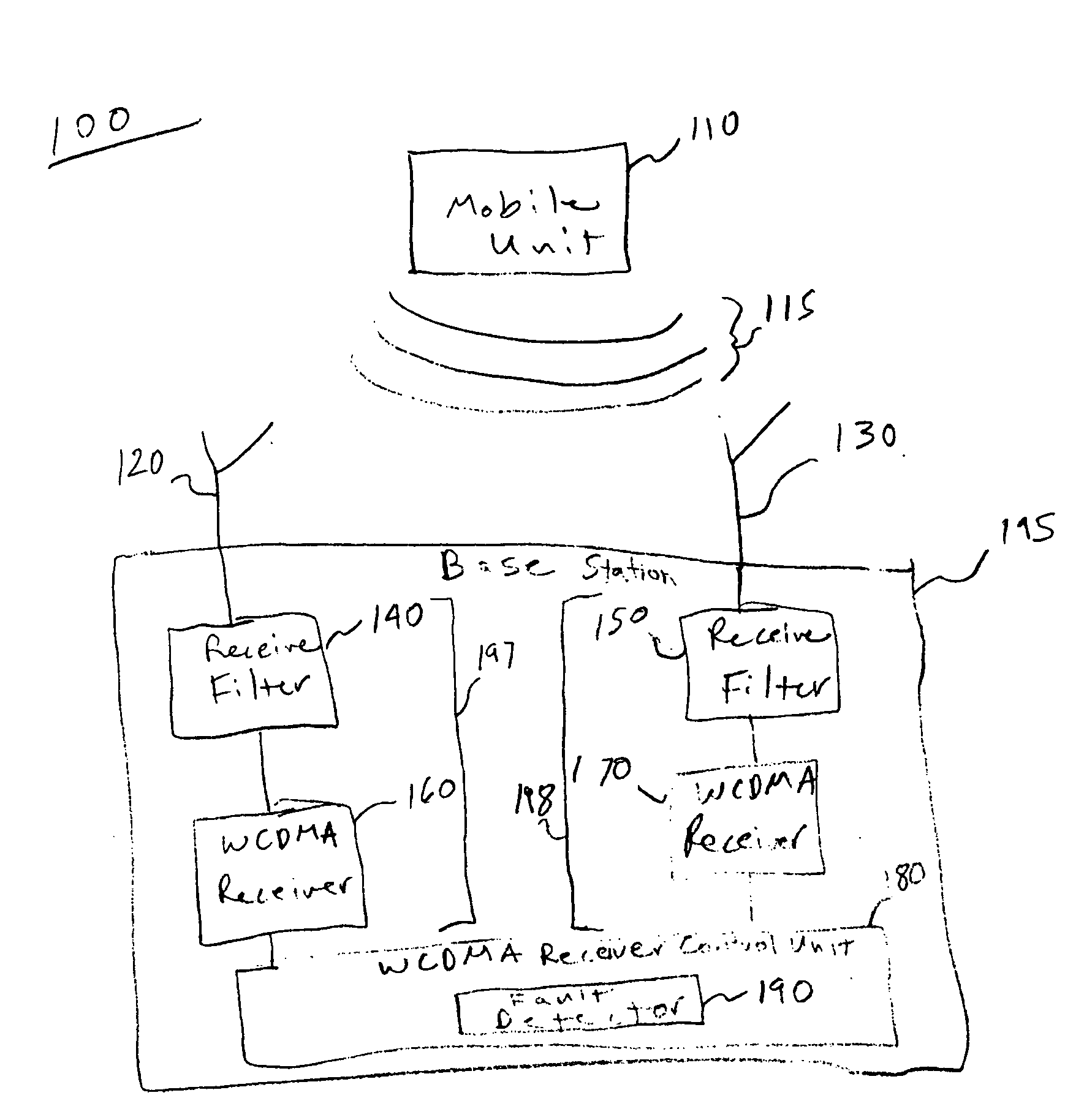
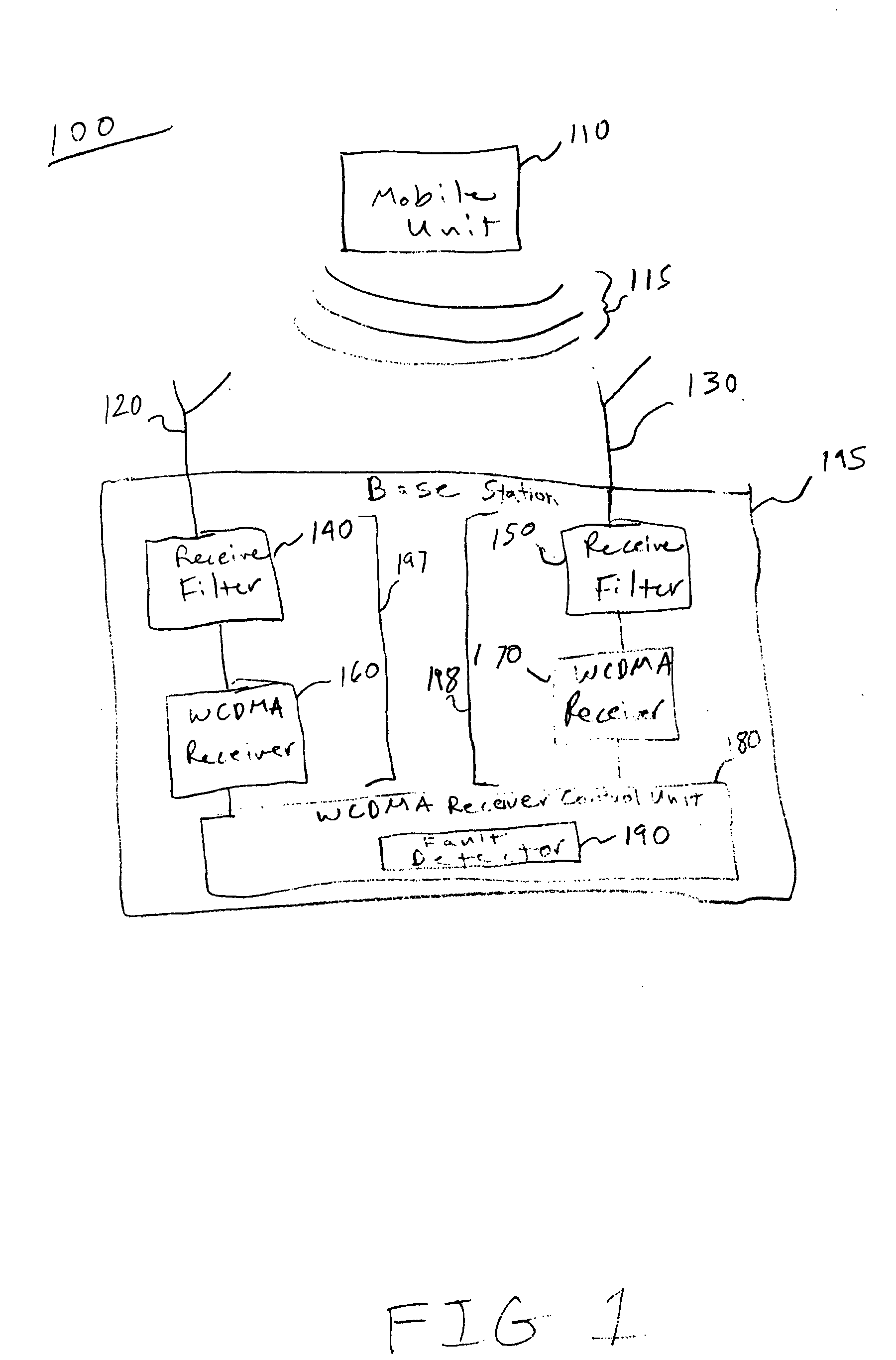
[0011] In an example embodiment of the invention, a fault detector may be used to determine whether a wideband code division multiple access (WCDMA) receiver is faulty. Information regarding an uplink signal of a mobile unit or other radio transmit device may be used by a fault detector to determine whether a fault in a receiver is present. The fault may be detected by taking advantage of existing WCDMA resources.

[0012] In an example embodiment of the invention, a fault detector receives classification values from at least two receivers located in a base station. The classification values may be based on the outputs of the at least two receivers. The at least two receivers process signal information of signals received from at least two antennas. Each of the antennas receive the same uplink signal from a mobile unit or other radio transmit device. First described is an example embodiment of a network that may be used in detecting a fault in a receiver. Next described is an example ...


PUM


Abstract

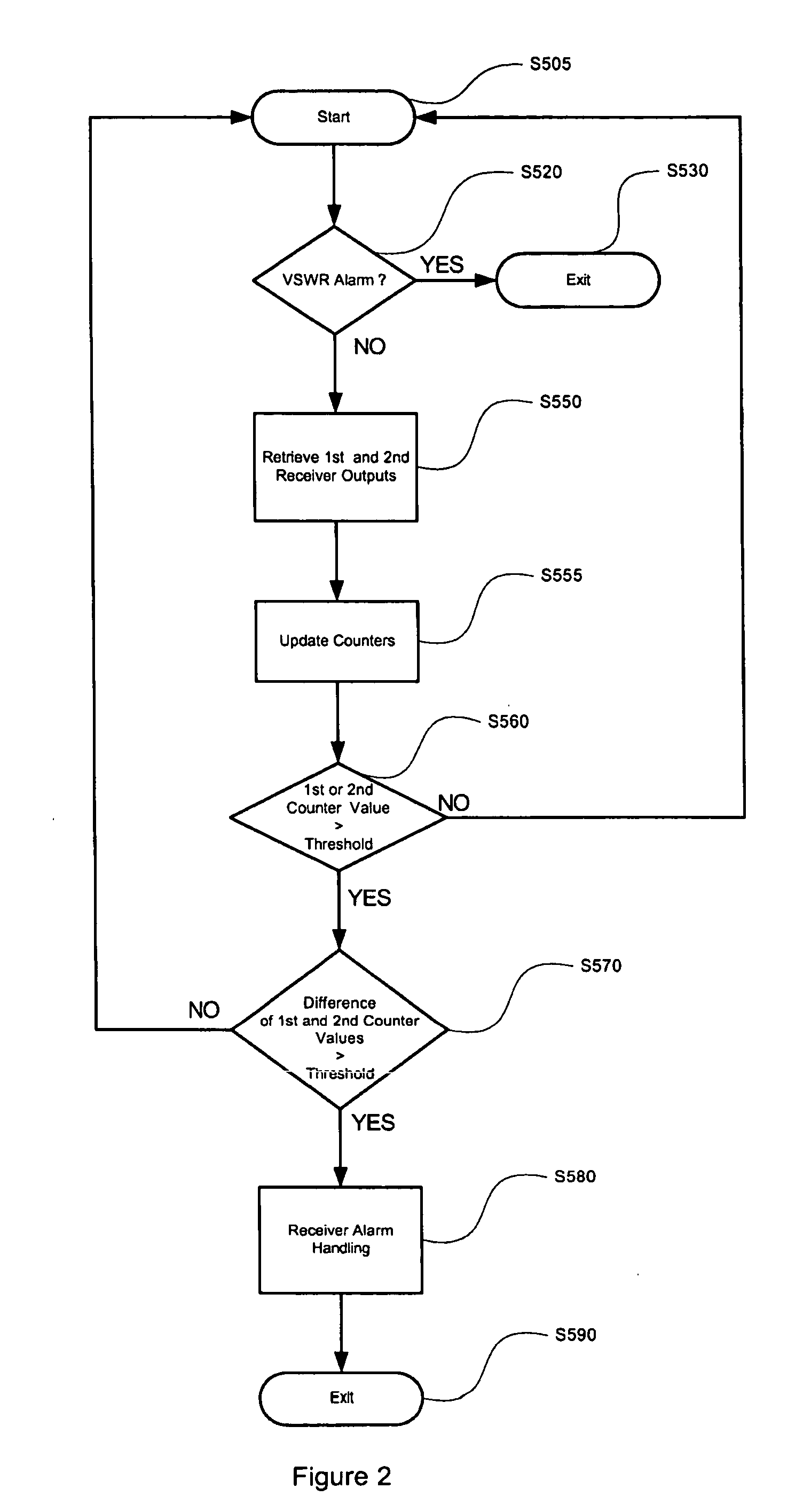
A system and method for receiving output signals from each receiver of multiple receivers, the output signals generated based on receipt of a same transmission; incrementing a count value associated with each receiver based on the output signals; and determining whether a fault in a receiver exists based on the associated count values of the receivers.

Description

BACKGROUND OF THE INVENTION [0001] Receivers in a multiple receiver system occasionally suffer from faults such as poor calibration or hardware malfunction. If the fault goes uncorrected, then information may not be properly received by the multiple receiver system causing faulty voice and / or data communications. Accordingly, multiple receiver systems tend to employ fault detection methods to find these faults and permit timely correction thereof. [0002] In a first example of a conventional fault detection method, a pilot signal is transmitted by a first radio system. The pilot signal is then received by a second radio system. The received pilot signal is processed by a second radio system receiver and then output to other components of the second radio system. The output power of the receiver in the second radio system, as a response to the pilot signal is then compared against the pilot signal transmit power from the first radio system. If a significant power difference exists bet...

Claims


Application Information

Patent Timeline
Patent Type & Authority Applications(United States)
IPC IPC(8): H04B17/00
CPCH04B17/21
Inventor LEHNERT, MARTINBOGNER, NORBERTHERTLEIN, GERHARD
Owner WSOU INVESTMENTS LLC
Learn More