Nanoelectronic capnometer adapter

Inactive Publication Date: 2005-11-03
NANOMIX
View PDF80 Cites 68 Cited by
  • Summary
  • Abstract
  • Description
  • Claims
  • Application Information

AI Technical Summary

Benefits of technology

[0023] The present invention overcomes the limitations of the prior art using a novel capnometer apparatus. A nanoelectronic capnometer system having aspects of the invention offers: (i) performance that matches or exceeds that of infrared technology, (ii) plug-and-play simplicit

Problems solved by technology

To meet the necessary specifications of such capnography device, current technology relies on bulky and expensive non-dispersive infrared absorption (NDIR) sensors to determine CO2 concentration.
The high cost and limitations of this technology restrict the use of capnography to high value

Method used


Image

  • Nanoelectronic capnometer adapter
  • Nanoelectronic capnometer adapter
  • Nanoelectronic capnometer adapter

Examples


Embodiment Construction

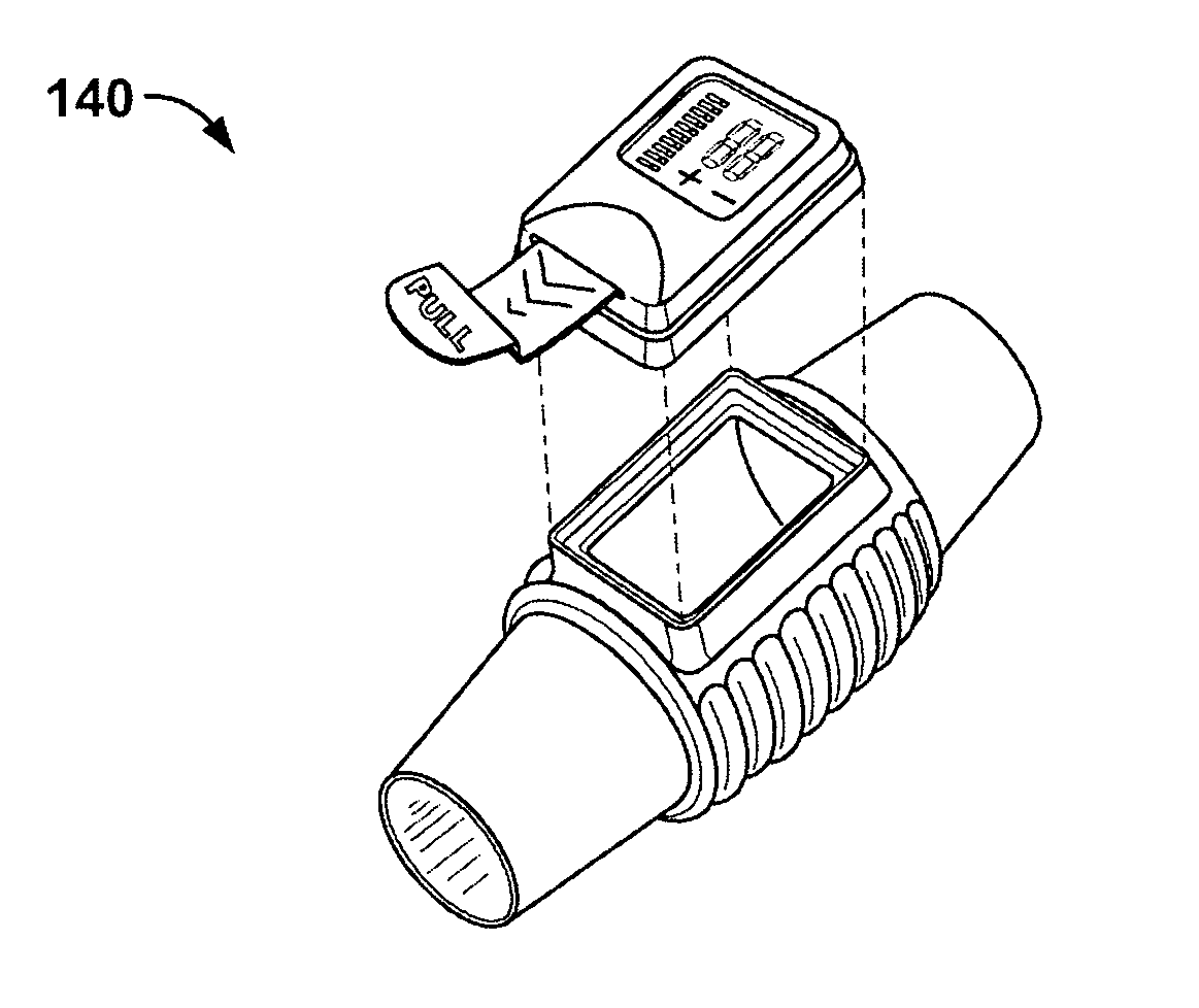
[0046] The embodiment of the invention incorporates a nanoelectronic capnometer into an adapter for patient airway monitoring. The resulting device seamlessly integrates into a mainstream capnography setup and delivers performance advantages over that of today's mainstream and sidestream NDIR capnometers.

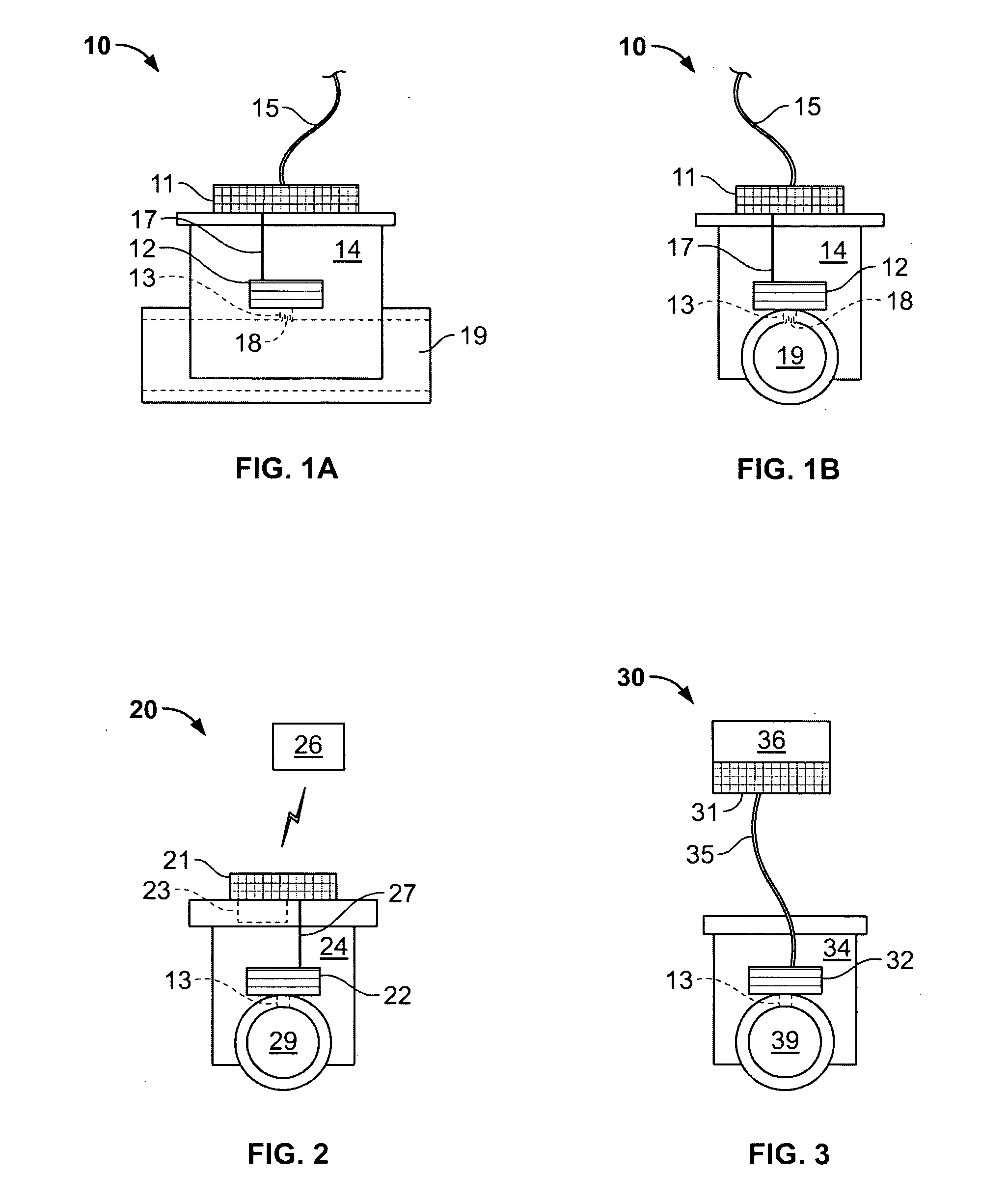
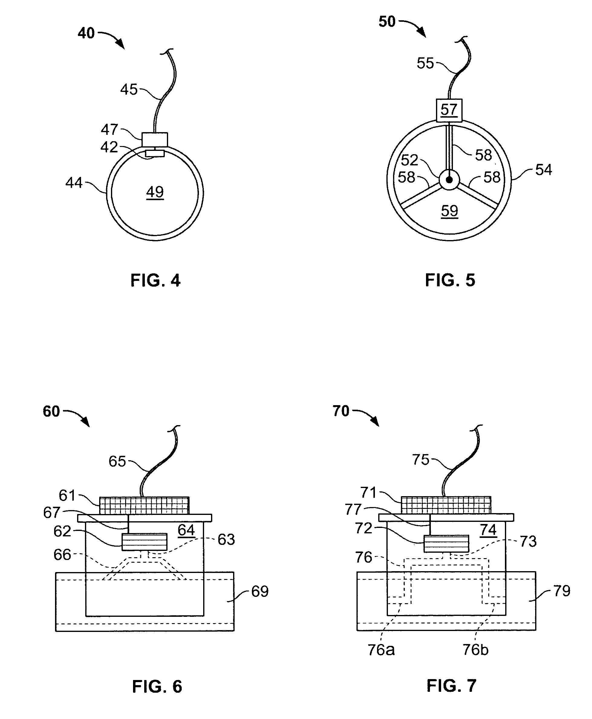
[0047]FIGS. 1-7 depict a number of different embodiments, in which the same or generally similar elements are identified by numbers, in which the last digit corresponds to the equivalent or corresponding element, as much as possible, in each figure, with the digits preceding the last digit corresponding to the figure number of each example embodiment.

[0048] Referring to FIGS. 1A and 1B, in an exemplary embodiment having aspects of the invention, the unit may be configured like conventional airway adapters, with an input and output for connecting tubing to an air channel 19 running through a housing 14. One opening of housing 14 may be fed by the patient's respiration and the other...


PUM


Abstract

A capnometer adaptor includes a nanostructure sensor configured to selectively respond to a gaseous constituent of exhaled breath, such as to carbon dioxide. The sensor may be provided as a compact and solid-state device, and may be adapted for a variety of respiratory monitoring applications.

Description

CROSS-REFERENCE TO RELATED APPLICATIONS [0001] This application claims priority pursuant to 35 U.S.C. § 119(e) to Provisional Application No. 60 / 531,079, filed Dec. 18, 2003, entitled “Nanoelectronic Capnometer Adapter,” and to Provisional Application No. 60 / 564,248, filed Apr. 20, 2004, entitled “Remotely Communicating, Battery-Powered Nanostructure Sensor Devices”. This application is a continuation-in-part of patent application Ser. No. 10 / 940,324, filed Sep. 13, 2004, entitled “Carbon Dioxide Nanoelectronic Sensor,” and of patent application Ser. No. 10 / 656,898, filed Sep. 5, 2003, entitled “Polymer Recognition Layers For Nanostructure Sensor Devices.” Each of the above-identified provisional and non-provisional patent applications is specifically incorporated herein, in its entirety, by reference.BACKGROUND OF THE INVENTION [0002] 1. Field of the Invention [0003] The present invention relates to an apparatus and method for mainstream patient airway medical monitoring, such as b...

Claims


Application Information

Patent Timeline
IPC IPC(8): A61B5/08G01N21/00G01N27/12G01N27/414G01N31/22G01N33/497
CPCB82Y10/00G01N33/497Y10S977/72G01N27/4146G01N27/4141
Inventor STAR, ALEXANDERWYATT, JEFFERYJOSHI, VIKRAMSTETTER, JOSEPH R.GRUNER, GEORGE
Owner NANOMIX
Why Eureka
Try Eureka