Cooled craniectomy

Inactive Publication Date: 2005-11-03
SEACOAST TECH
View PDF3 Cites 2 Cited by
  • Summary
  • Abstract
  • Description
  • Claims
  • Application Information

AI Technical Summary

Benefits of technology

[0007] The present invention advantageously provides a method and system for reducing the extent and duratio

Problems solved by technology

With increased swelling, the brain can no longer be contained in the cranium and thus shifts, with the brain stem possibly becoming twisted.
Blood f

Method used


Image

  • Cooled craniectomy
  • Cooled craniectomy
  • Cooled craniectomy

Examples


Embodiment Construction

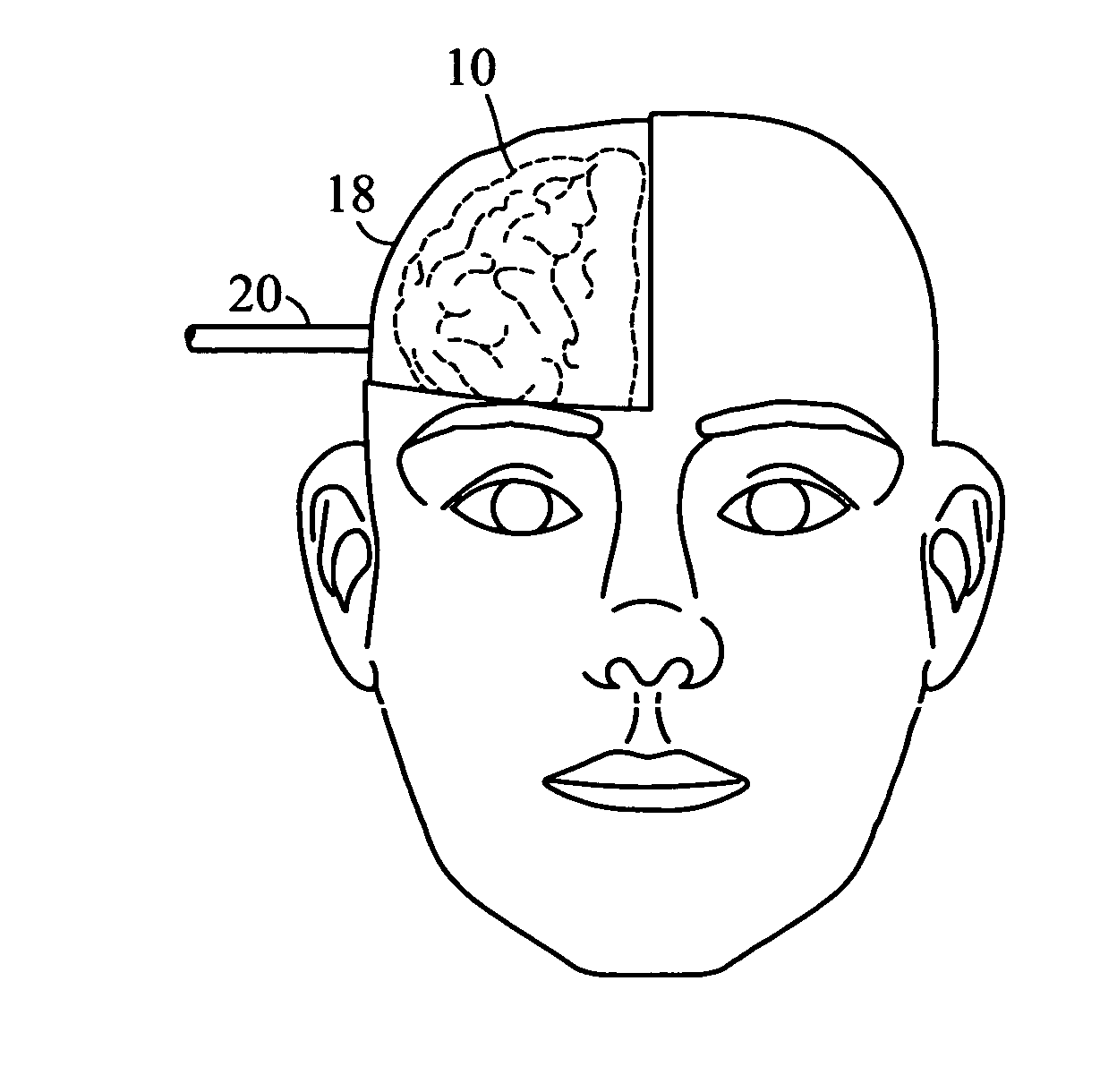
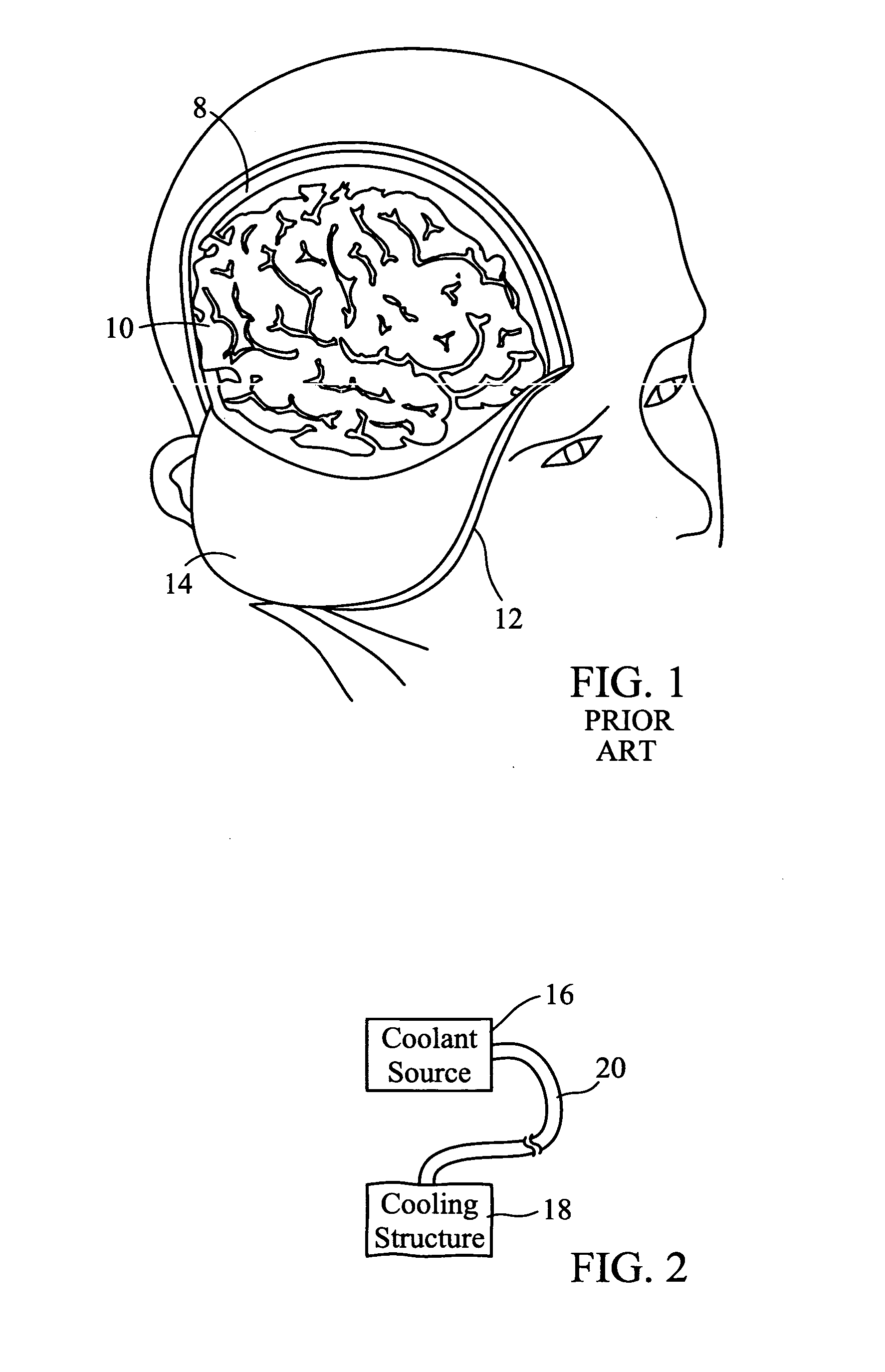
[0014] The present invention includes a medical procedure for inhibiting swelling of the brain by locally cooling the brain. In an exemplary procedure, known medical techniques are used to remove a relatively large portion of the skull, such as in the decompressive craniectomy illustrated in FIG. 1. Although a particular location is shown for the cut boundaries, as is a specific size and shape for the cut bone, as used herein, performance of a decompressive craniectomy in intended to encompass any procedure wherein the purpose of the procedure is to allow brain tissue to swell relatively unrestricted and to immediately reduce intracranial pressure by removing at least 2 cm2 of bone. Often, much more bone is removed. Again, using known techniques, the dura mater is cut to expose brain tissue or, alternatively, the dura is left intact.

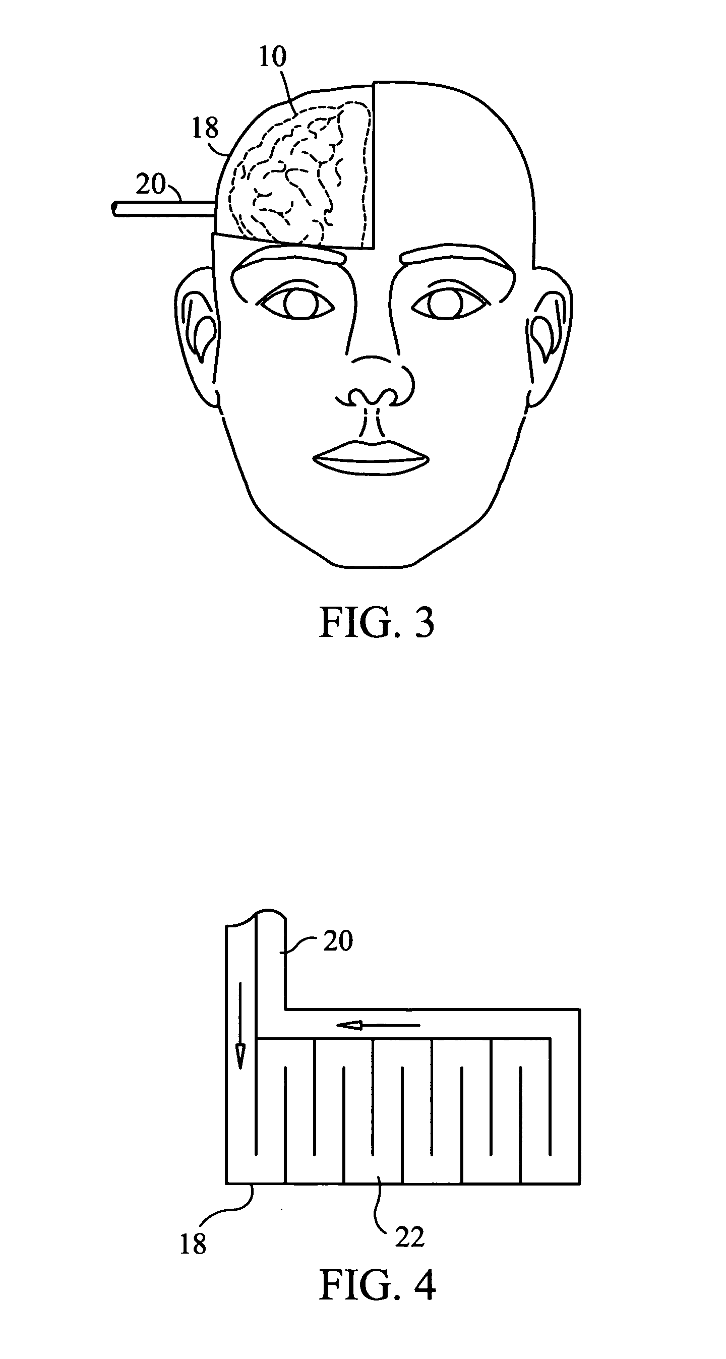
[0015] Having determined whether the brain is to be cooled directly or indirectly through the dura, a cooling structure as described below is placed di...


PUM


Abstract

A method and system are provided for reducing the extent and duration of brain swelling in a trauma or stroke victim requiring decompressive craniectomy. In an exemplary method, a medical procedure for inhibiting swelling of the brain includes the steps of performing a decompressive craniectomy to expose intracranial tissue, placing a cooling structure on the exposed intracranial tissue, and cooling the exposed intracranial tissue with the cooling structure. An exemplary system for performing the method includes a source of coolant, a cooling structure, and an umbilical connecting the source of coolant and the cooling structure and conducting cooling fluid therebetween, wherein the cooling structure is dimensioned to cover substantially all exposed intracranial tissue.

Description

CROSS-REFERENCE TO RELATED APPLICATION [0001] n / a STATEMENT REGARDING FEDERALLY SPONSORED RESEARCH OR DEVELOPMENT [0002] n / a FIELD OF THE INVENTION [0003] The present invention relates to a medical method and apparatus for treating swelling of the brain. BACKGROUND OF THE INVENTION [0004] In head injuries and stroke, neurological damage generally is caused by swelling of the brain within the confined space of the skull. With increased swelling, the brain can no longer be contained in the cranium and thus shifts, with the brain stem possibly becoming twisted. Blood flow to the brain is impeded resulting in brain damage or death. In trauma cases, further complications can result from a badly contused brain tissue. [0005] The traditional approach to dealing with brain swelling in trauma situations has been to medically manage the patient with various pharmaceuticals, remove brain tissue, or in some cases remove entire lobes of the brain, with certain brain damage resulting. However, in...

Claims


Application Information

Patent Timeline
IPC IPC(8): A61F7/00A61F7/02A61F7/10A61F7/12
CPCA61F7/10A61F2007/0056A61F2007/0002
Inventor LARNARD, DONALD J.
Owner SEACOAST TECH
Why Eureka
Try Eureka