Aerodynamic structure for aircraft wing

a technology for aerodynamic structures and aircraft wings, applied in heat reducing structures, air-flow influencers, transportation and packaging, etc., can solve the problems of airflow separation, degrading downstream boundary layers, and exposed inner faces of slat recesses, so as to improve aerodynamic and/or flight properties of wings, the effect of minimising drag

Active Publication Date: 2020-05-07
AIRBUS OPERATIONS LTD
View PDF0 Cites 4 Cited by
  • Summary
  • Abstract
  • Description
  • Claims
  • Application Information

AI Technical Summary

Benefits of technology

[0006]By providing an aerodynamic structure adjacent to the recess edge which is shaped to encourage attachment of airflow onto the upper surface, local flow separation may be reduced compared to a case in which such an aerodynamic structure is not present at the recess edge. By reducing flow separation due to the recess edge, the energy of the downstream boundary layer on the wing upper surface may be increased, such that the boundary layer is more able to sustain other causes of flow separation. Further, by reducing local flow separation at the recess edge and improving the downstream boundary layer, stall may be delayed and the maximum lift coefficient of the wing may be increased.
[0017]Preferably, the aerodynamic structure is arranged to be exposed to airflow when the slat is in the stowed configuration. By mounting the aerodynamic structure on the upper surface of the wing, an existing aircraft and / or aircraft wing may be retro-fitted with the aerodynamic structure, enabling a reduction in local flow separation in the vicinity of wing planform discontinuities whilst reducing an extent and / or complexity of aircraft modification required compared to some other retro-fitting methods. Further, retro-fitting the aerodynamic structure onto an existing wing may be less costly, use less material and / or be less time-consuming than constructing a new wing incorporating the aerodynamic structure.

Problems solved by technology

However, with the slat deployed, the inner faces of the slat recess may be exposed.
However, separation of the airflow may occur as the airflow is forced over sharp edges.
Such local flow separation can degrade the downstream boundary layer, e.g. by reducing the energy of the downstream boundary layer, which in turn renders the downstream boundary layer more susceptible to other causes of flow separation, e.g. adverse pressure gradients or surface imperfections.
The local flow separation occurring adjacent to discontinuities on the wing planform can limit or reduce the maximum lift coefficient of the wing, and consequently of the aircraft as a whole, thereby affecting the performance of the aircraft.

Method used


Image

  • Aerodynamic structure for aircraft wing
  • Aerodynamic structure for aircraft wing
  • Aerodynamic structure for aircraft wing

Examples


first embodiment

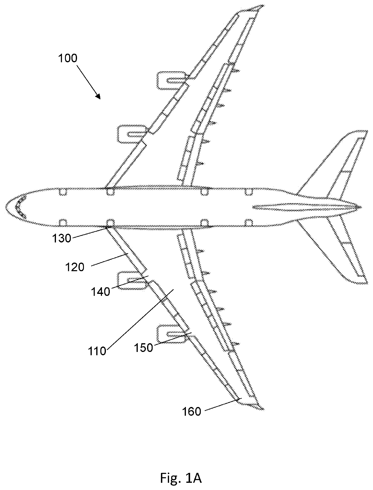
[0045]In the first embodiment, the upper surface of the wing is at a wing root region. For example, the upper surface of the wing may be formed by a wing root fairing. As such, the structure 310 is arranged in the vicinity of a wing root, it being understood that the structure 310 may be arranged on other regions of the wing upper surface in other embodiments.

[0046]The aerodynamic structure 310 is arranged adjacent to the recess edge 330. As such, in the first embodiment, the structure 310 is arranged adjacent to an end face 340 of the slat recess. The structure 310 may abut the recess edge 330, e.g. be in direct contact with the recess edge 330, or may be separated from the recess edge 330 but still be in relatively close proximity to the recess edge 330. The aerodynamic structure 310 is considered to be adjacent to the recess edge 330 in both of the above cases.

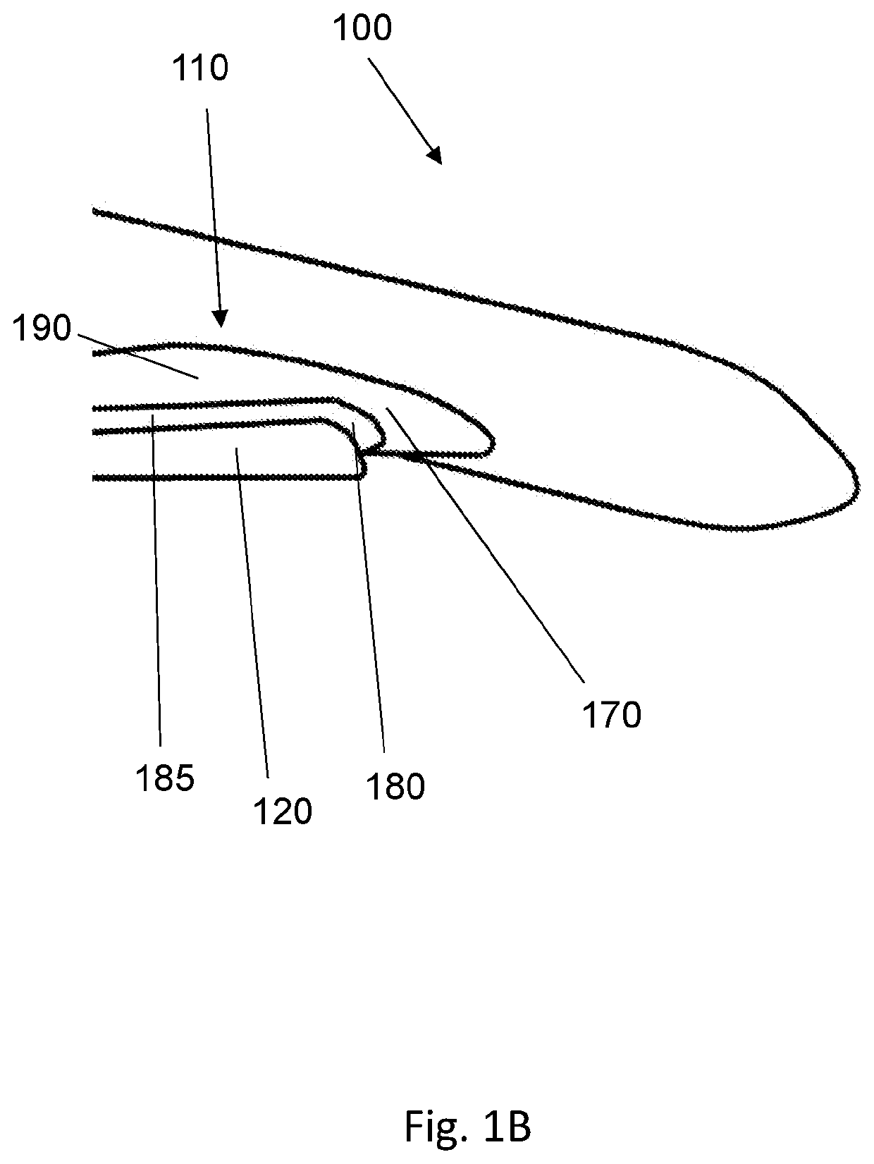
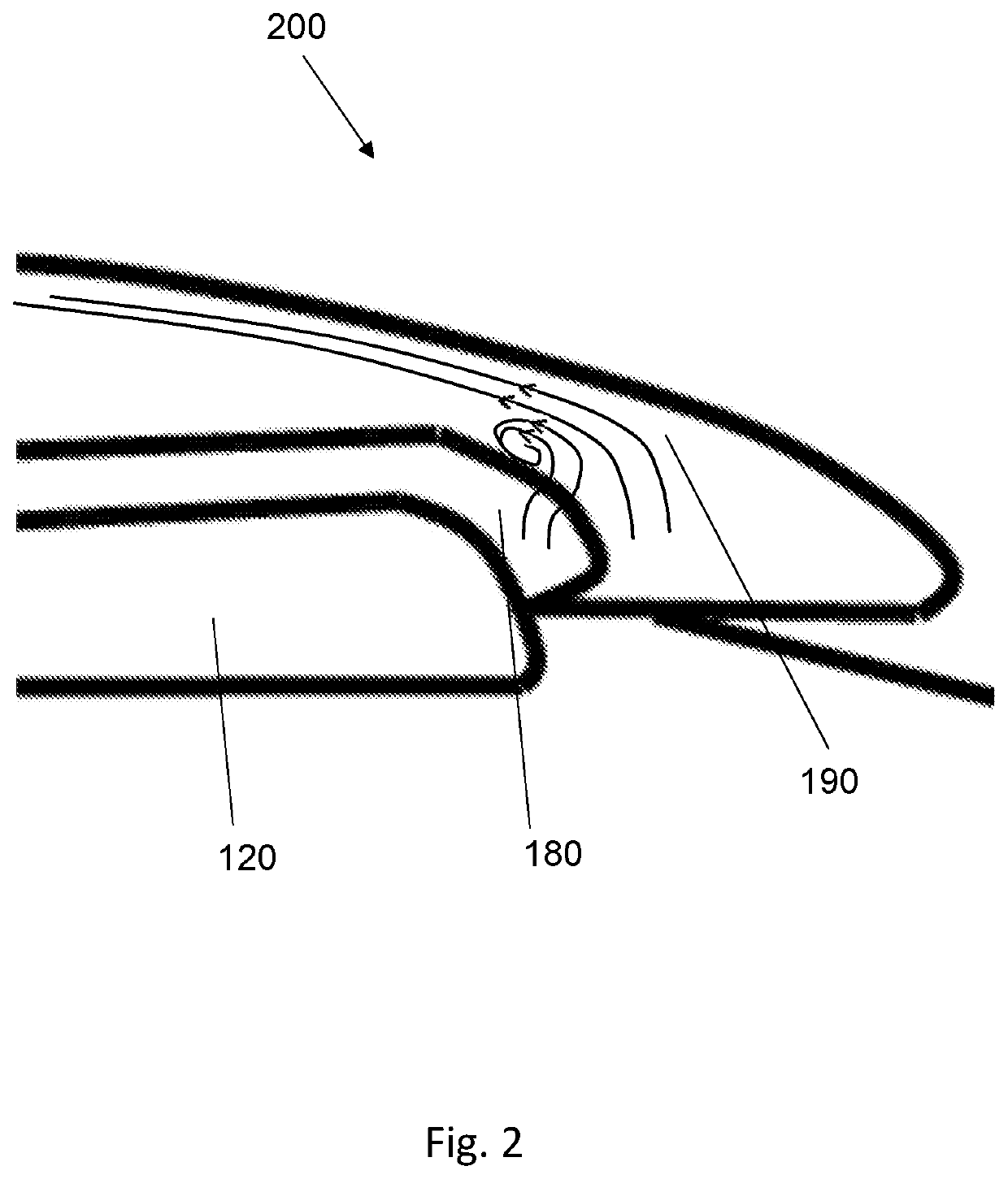
[0047]The aerodynamic structure 310 provides the wing upper surface 320 with additional volume and height in the vicinity...

second embodiment

[0061]FIG. 5 shows a diagonal perspective view of an aerodynamic structure 510 applied to an upper surface of a wing, according to a

[0062]In this embodiment, the structure 510 is on the upper surface of the wing adjacent to a junction between an outboard end of a slat and a wing tip region. The wing tip region may include a winglet. The junction forms an exposed recess edge when the slat is deployed. The junction is an example of a wing discontinuity. The structure 510 is arranged to encourage air flowing over the recess edge onto the wing upper surface to remain attached.

third embodiment

[0063]FIG. 6 shows a diagonal perspective view of an aerodynamic structure 610 applied to an upper surface of a wing, according to a

[0064]In this embodiment, the structure 610 is on the upper surface of the wing at a wing pylon region. The pylon region may include a pylon, or station, at which an engine is mounted to the wing. The structure 610 is at a junction between an inboard end of a slat and the wing pylon region. In some cases, the structure 610 is at a junction between an outboard end of a slat and the wing pylon region. The junction forms an exposed recess edge when the slat is deployed. The junction is an example of a wing discontinuity. The structure 610 is arranged to encourage air flowing over the recess edge onto the wing upper surface to remain attached.


PUM


Abstract

An aerodynamic structure for use on an upper surface of an aircraft wing is disclosed. The wing includes a slat operable between a stowed configuration in which the slat is stowed in a slat recess of the wing, and a deployed configuration in which the slat extends out of the slat recess. When the slat is in the deployed configuration, an end face of the slat recess is exposed, the end face intersecting with the upper surface of the wing at a recess edge. The aerodynamic structure, adjacent to the recess edge, has a volume shaped to encourage air flowing over the recess edge onto the upper surface during flight, to remain attached.

Description

BACKGROUND OF THE INVENTION[0001]The present invention concerns aircraft wings. More particularly, but not exclusively, the invention concerns the provision of aerodynamic structures for use on aircraft wings.[0002]Aircraft wings may comprise discontinuities, e.g. sharp corners, in some wing regions, which may affect airflow around the wing, and consequently the performance of the aircraft during flight. Such discontinuities may be found, for example, as part of a slat recess, or cavity, for housing a leading-edge slat. A leading-edge slat is an aerodynamic surface on the leading edge of a wing which, when deployed, allows the wing to operate at a higher angle of attack. The slat may be stowed in the slat recess during cruise, and may be deployed to extend out of the slat recess during take-off and / or landing. With the slat stowed in, and flush with, the slat recess, the upper surface of the slat may be substantially continuous with the upper surface of the wing, thereby concealing ...

Claims


Application Information

Patent Timeline
Patent Type & Authority Applications(United States)
IPC IPC(8): B64C21/02B64C3/28B64C7/00B64C5/08
CPCB64C5/08B64C3/28B64C7/00B64C21/02B64C3/36B64C9/22B64C23/06B64C21/00B64C23/00B64C2003/148B64C2230/00Y02T50/30B64C21/10B64C23/005B64C23/065
Inventor HUI, CHING-YULYONS, NEIL JOHN
Owner AIRBUS OPERATIONS LTD
Why Eureka
Try Eureka