
Modular implant with a micro-motion damper

a technology of modular implants and dampers, applied in the field of orthopaedics, can solve the problems of reducing the useful life of some modular implants, small amounts of undesirable motion, and degrading alignment and/or stability

Inactive Publication Date: 2005-11-03
ZIMMER TECH INC
View PDF17 Cites 41 Cited by
  • Summary
  • Abstract
  • Description
  • Claims
  • Application Information

AI Technical Summary

Benefits of technology

[0005] In another alternative embodiment, the present invention provides an apparatus for forming a prosthetic joint between a first body part and a second body part. The apparatus includes a first means for coupling the prosthetic joint to the first body part, a second means for coupling the prosthetic joint to the second body part, a means for articulating the first means relative to the second means, and a means for damping micro-motion within the prosthetic joint.

Problems solved by technology

However, some modular designs allow small amounts of undesirable motion (“micro-motion”) between components that should stay firmly locked together after assembly.
Such micro-motion is an undesirable source of wear that can degrade alignment and / or stability of some prostheses over time, or otherwise reduce the useful life of some modular implants.

Method used


Image

  • Modular implant with a micro-motion damper
  • Modular implant with a micro-motion damper
  • Modular implant with a micro-motion damper

Examples


Embodiment Construction

)

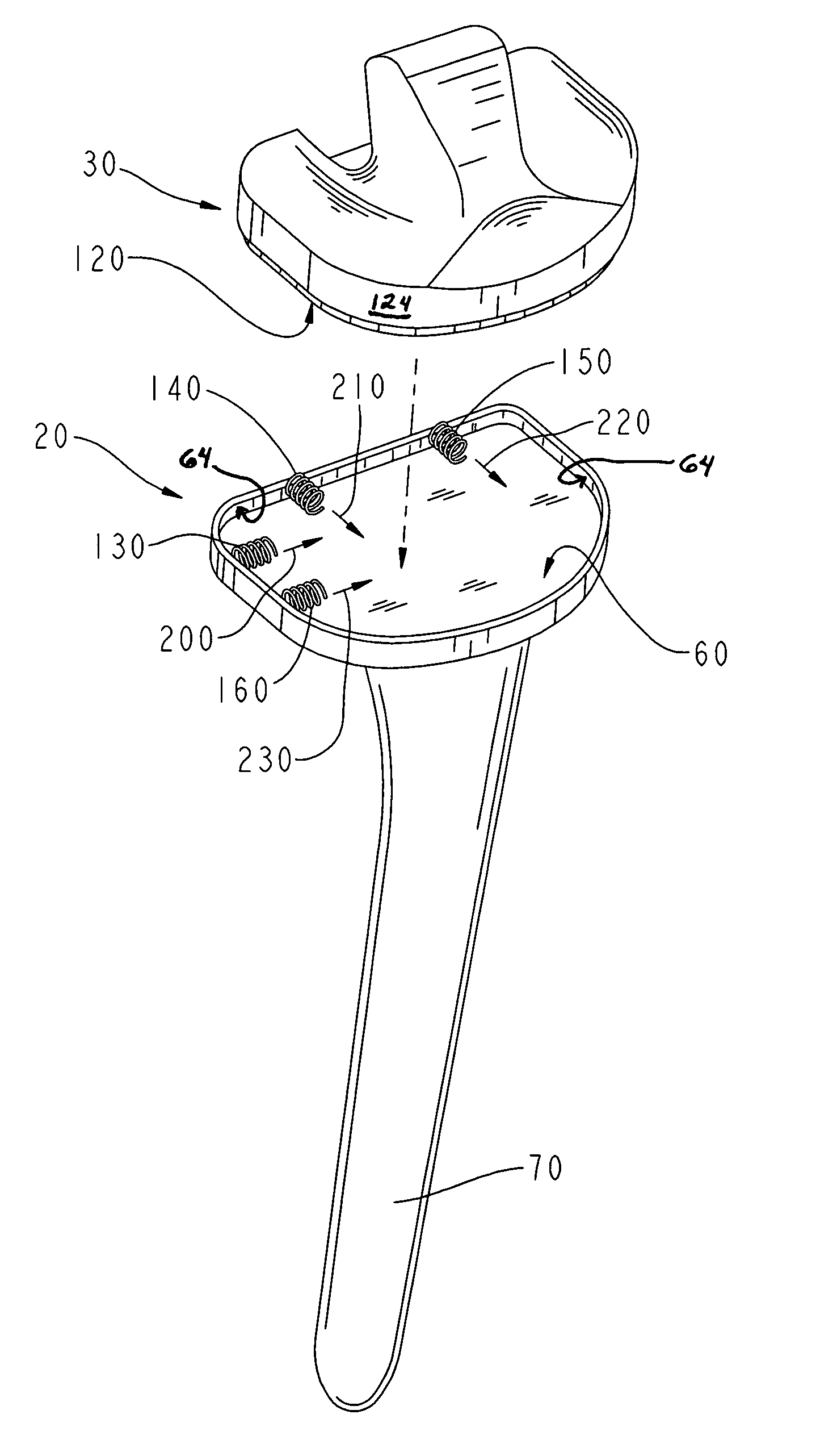
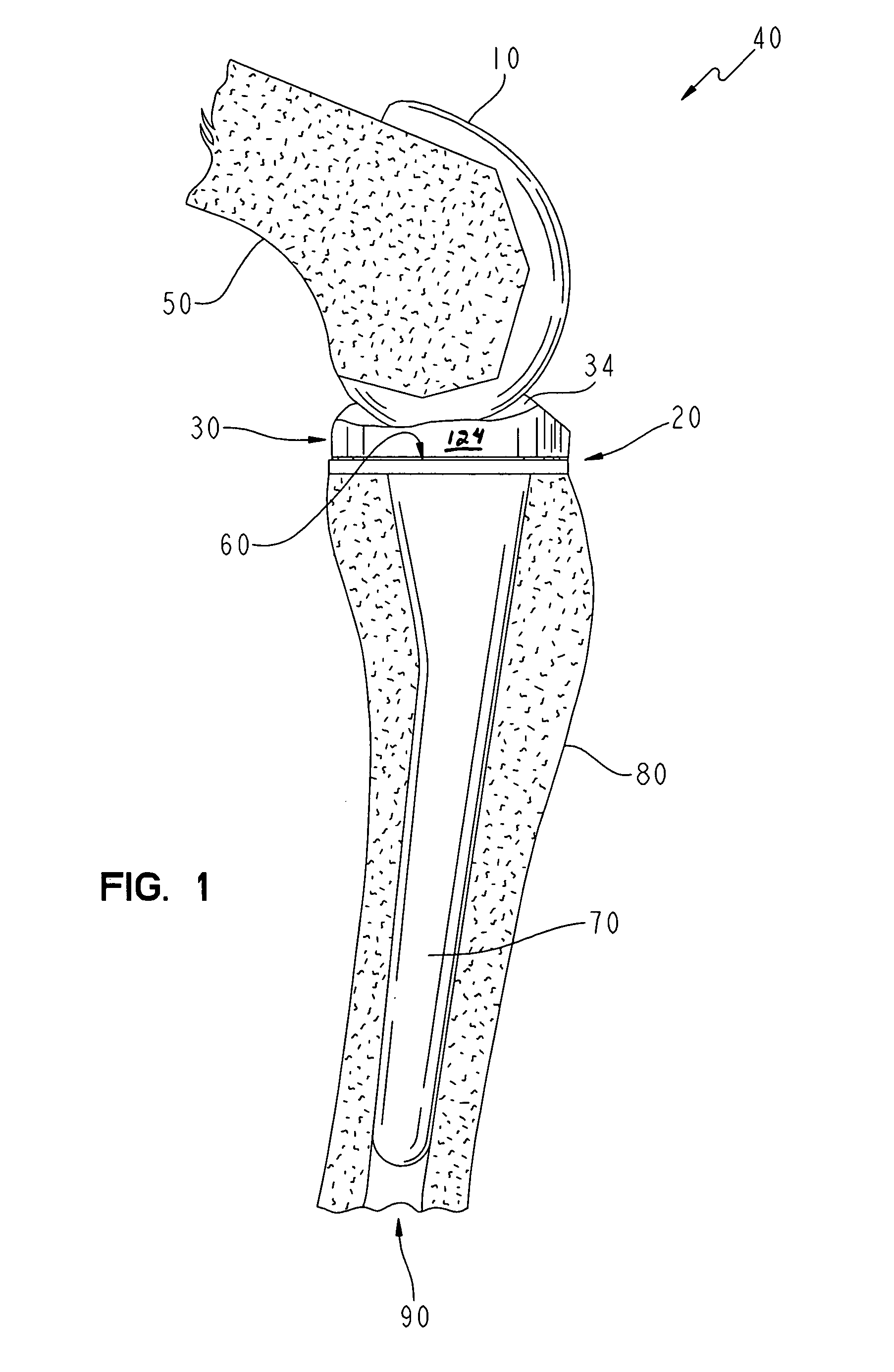
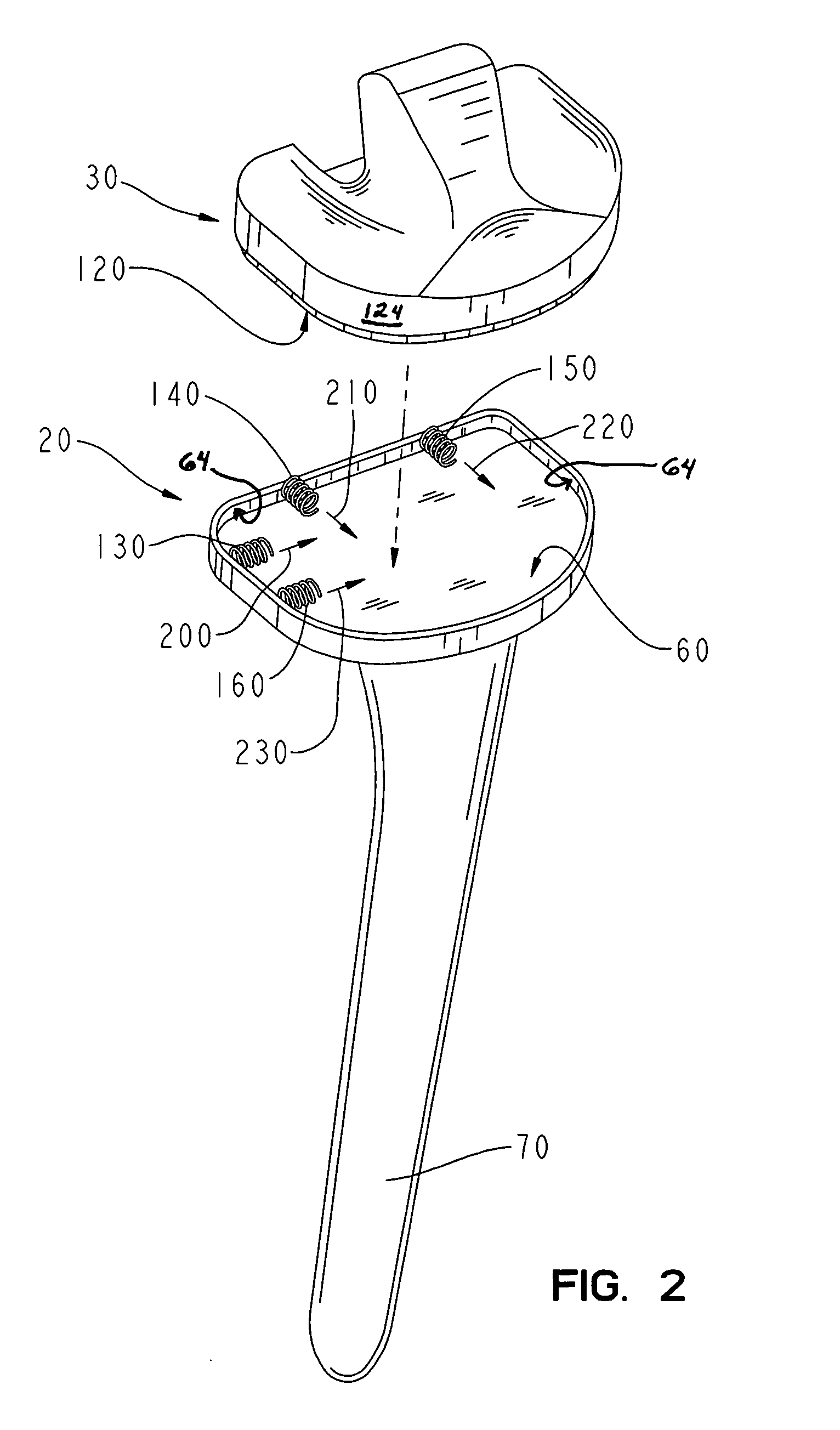
[0009]FIG. 1 shows a lateral view of an exemplary modular prosthetic knee assembly 40 according to the present invention. Knee assembly 40 includes a femoral component 10, a tibial component 20, and a bearing 30. Femoral component 10 is configured in a known manner to fit onto a resected distal femur 50 and is made from a metallic material or alloy such as cast Co—Cr—Mo or any other suitable biocompatible material(s). Tibial component 20 defines a recessed tibial baseplate 60 (see also FIG. 2) with an inner sidewall 64 (not indicated in FIG. 1; but see FIG. 2), and defines an elongated stem 70. Tibial component 20 is configured in a known manner to secure to a proximal tibia 80 via insertion of stem 70 into an intramedullary canal 90 of tibia 80 and is made from a metallic material or alloy such as cast Co—Cr—Mo or any other suitable biocompatible material(s). It should be appreciated that in alternative embodiments, stem 70 may be replaced with any other suitable bone fixation fea...


PUM


Abstract

A modular implant is provided. The modular implant includes a first orthopaedic component, a second orthopaedic component coupled to the first orthopaedic component, and a micro-motion damper interposed between the first orthopaedic component and the second orthopaedic component.

Description

FIELD OF THE INVENTION [0001] The present invention relates generally to the field of orthopaedics, and, more particularly, to modular implants. BACKGROUND [0002] Many conventional orthopaedic implant assemblies are modular. Among other things, modularity facilitates the intra-operative versatility of combining various components best suited for any particular patient. However, some modular designs allow small amounts of undesirable motion (“micro-motion”) between components that should stay firmly locked together after assembly. Such micro-motion is an undesirable source of wear that can degrade alignment and / or stability of some prostheses over time, or otherwise reduce the useful life of some modular implants. SUMMARY OF THE INVENTION [0003] The present invention provides a modular implant including a first orthopaedic component, a second orthopaedic component coupled to the first orthopaedic component, and a micro-motion damper interposed between the first orthopaedic component ...

Claims


Application Information

Patent Timeline
IPC IPC(8): A61F2/00A61F2/30A61F2/34A61F2/38A61F2/46
CPCA61F2/389A61F2002/30387A61F2002/3051A61F2002/30563A61F2002/30568A61F2310/00029A61F2002/30604A61F2002/3082A61F2002/30878A61F2220/0025A61F2002/30571A61F2002/30507
Inventor YAO, JIAN Q.
Owner ZIMMER TECH INC
Learn More