Electronic control device and data adjustment method

a technology of electronic control device and data adjustment, which is applied in the direction of electrical control, instruments, memory allocation/allocation/relocation, etc., can solve the problems of inability to perform data reading, excessive time required for data rewrite processing in flash eeprom, and considerable amount of trouble, so as to efficiently rewrite large quantities of control data

Inactive Publication Date: 2005-11-03
RENESAS ELECTRONICS CORP
View PDF2 Cites 11 Cited by
  • Summary
  • Abstract
  • Description
  • Claims
  • Application Information

AI Technical Summary

Benefits of technology

[0022] By means of this invention, pre-adjustment control data, which is to be adjusted and is stored in the data storage area, is adjusted in substitute memory to values appropriate to the device to be controlled, and thereafter the adjusted control data is written to the data storage area separate from the data storage area in which the pre-adjustment control data had been stored, and which is the data area which can be written independently of the data storage area in which the pre-adjustment control data had been stored, so that control data adjustment is possible while continuing adjustment processing, and, for example, adjustment processing of control data in the next data storage area can be executed in succession. By this means, while executing adjustment processing to adjust control data to values appropriate to the device to be controlled, the adjusted control data can be written, so that even substitute memory with small storage capacity can be used to efficiently rewrite large quantities of control data.

Problems solved by technology

However, while data rewrite processing is being performed in the flash EEPROM, data reading cannot be performed.
Further, the time required for data rewrite processing in the flash EEPROM is extremely long compared with the time required for overwriting in RAM (Random Access Memory).
Hence when performing a plurality of calibration operations for a single flash EEPROM, the above-described processing must be repeated for each calibration operation, and a considerable amount of trouble must be taken.
However, in the case of such a conventional adjustment method it is not possible to write back adjusted control parameters after calibration while the application program is being executed, and a dedicated program must be executed after execution of the application program to write back the data in RAM to the data area in flash memory.
That is, because flash memory cannot simultaneously execute write and read operations, while writing of adjusted control parameters is being executed, control parameters cannot be read from flash memory.
As explained above, the time required for data writing to flash memory is extremely long, and so the application program must be terminated.
However, if the large quantity of control parameters is to be adjusted all at once, RAM with a large storage capacity must be installed, and there is the problem that the impact on costs is considerable.
If on the other hand a small amount of RAM is to be used in adjustment processing of a large quantity of control parameters, as explained above, the application program must be halted temporarily, and processing to write back data to RAM must be repeated a plurality of times, so that there is the problem that an extremely long time is required for control parameter adjustment.

Method used


Image

  • Electronic control device and data adjustment method
  • Electronic control device and data adjustment method
  • Electronic control device and data adjustment method

Examples


embodiment 1

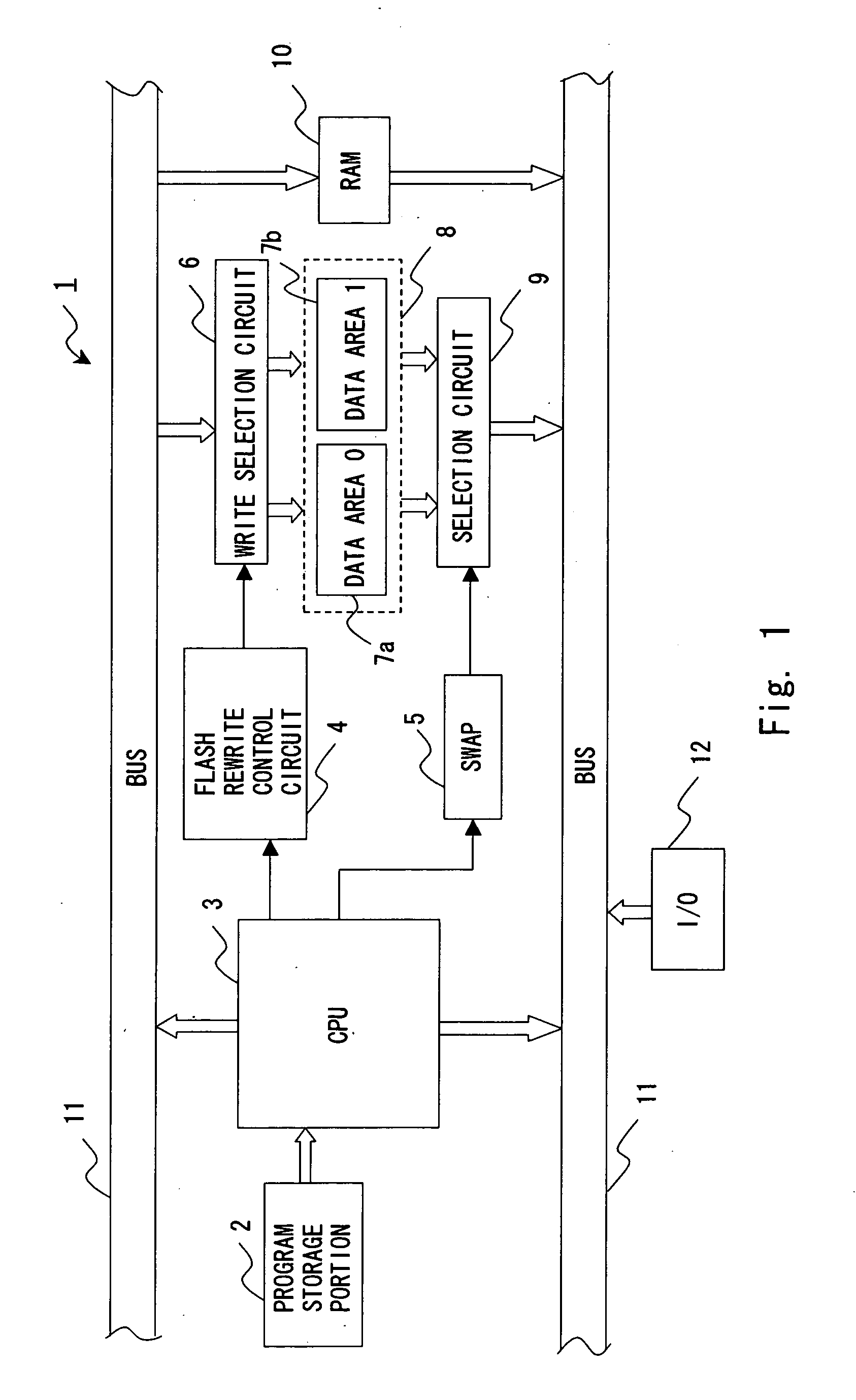
[0037]FIG. 1 is a block diagram showing a microcomputer 1 in this embodiment of the invention. As shown in FIG. 1, the microcomputer 1 has a program storage portion 2; CPU (Central Processing Unit) 3; flash memory (flash EPROM (Erasable Programmable Read-Only Memory)) 8; RAM 10; write selection circuit 6; read selection circuit 9; flash rewrite control circuit 4; swap register 5; I / O interface portion 12; and database 11 to exchange data with the CPU 3, write selection circuit 6, read selection circuit 9, RAM 10, and similar.

[0038] In the program storage portion 2 is stored an application program which executes control of equipment to be controlled (hereafter “the controlled equipment”). As is explained below, this program storage portion 2 is flash memory, ROM (Read-Only Memory) or other nonvolatile memory, in which is stored the application program to execute control of the controlled equipment using control data.

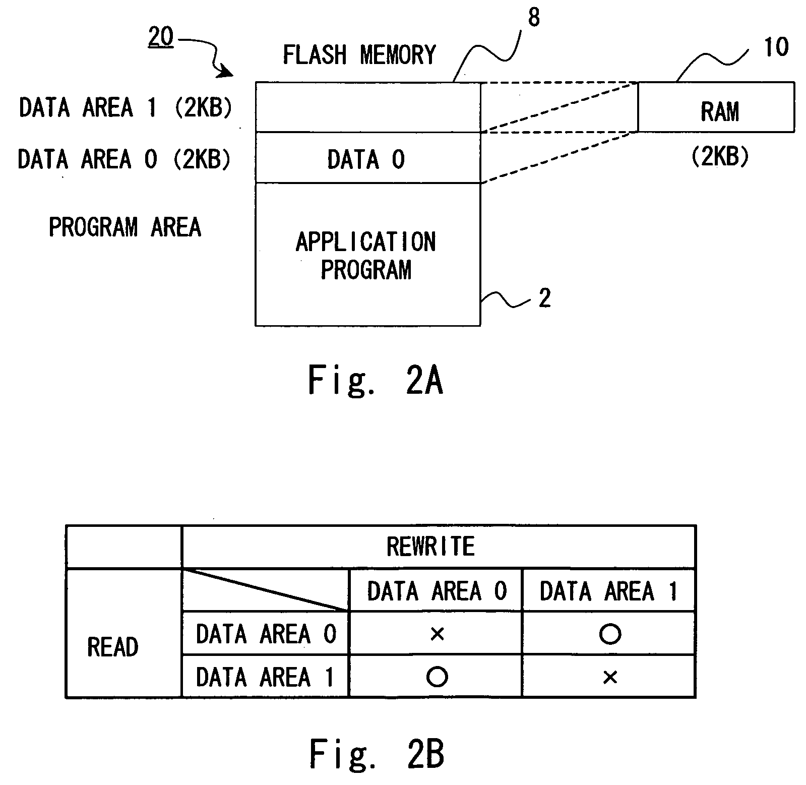
[0039] The flash memory 8 has a plurality of data areas (data stor...

embodiment 2

[0065] Next, Embodiment 2 of the invention is explained. FIG. 6 is a block diagram showing the microcomputer 21 in Embodiment 2 of the invention. The above-described flash memory had two data areas, but the flash memory in this embodiment has four data areas. Otherwise the configuration is similar to Embodiment 1 shown in FIG. 1; constituent components similar to those in FIG. 1 are assigned the same symbols, and detailed explanations are omitted.

[0066] As shown in FIG. 6, the microcomputer 21 of this embodiment has flash memory 28 comprising a first memory macro 27a as a first nonvolatile storage portion having data areas 0 and 1, and a second memory macro 27b as a second nonvolatile storage portion having data areas 2 and 3. Any one data area in the first memory macro 27a or second memory macro 27b is used as a data area for normal reading of the latest control data by the CPU 3, and another data area is used as an adjustment area for writing adjusted control data after optimizat...


PUM


Abstract

A microcomputer has flash memory having at least two data areas, others of which can be written while one is being read, and substitute RAM which is used when adjusting control data prior to adjustment (pre-adjustment control data) which is stored in for example one of the data areas; the CPU controls equipment to be controlled by executing a program in a program storage portion using control data in one of the data areas. In adjustment processing of the control data, the control data in one of the data areas is copied to RAM and adjusted to values appropriate to the equipment to be controlled, and the adjusted control data is written to another data area, after which the addresses in a memory map of the two data areas are swapped. Subsequently, the CPU controls the equipment using the adjusted control data which physically is stored in the other data area.

Description

BACKGROUND OF THE INVENTION [0001] 1. Field of the Invention [0002] This invention relates to an electronic control device and data adjustment method for an electronic control device which use control data to control a controlled portion, and in particular relates to an electronic control device and a data adjustment method for an electronic control device enabling adjustment of control data, while executing control of the controlled portion. [0003] 2. Description of the Related Art [0004] In general, control programs, control parameters, and other data (hereafter called “control data”) used to control equipment or similar is often stored in nonvolatile memory (ROM) which is not erased even if a battery is removed, for supply to users. [0005] Further, there are cases in which, after installing an electronic control device in a system, it is desired to adjust the control data according to the characteristics of the equipment to be controlled (calibration). Hence the control data is s...

Claims


Application Information

Patent Timeline
Patent Type & Authority Applications(United States)
IPC IPC(8): F02D45/00G06F12/00G06F12/02G06F12/06
CPCG06F12/0638G06F12/0246
Inventor OBA, KAORI
Owner RENESAS ELECTRONICS CORP
Why Eureka
Try Eureka