
Apparatus and method of rewriting firmware

a firmware and firmware technology, applied in the field of firmware rewriting, can solve the problems of not always efficient rewriting of firmware, more types of commands which are transmitted from the main controller, and the contents of statuses to be returned to the main controller are more complex

Inactive Publication Date: 2004-04-08
SEIKO EPSON CORP
View PDF11 Cites 34 Cited by
  • Summary
  • Abstract
  • Description
  • Claims
  • Application Information

AI Technical Summary

Benefits of technology

The present invention relates to a technique for rewriting firmware in an image forming apparatus. The invention aims to improve the efficiency of rewriting firmware by allowing the engine controller to control its own firmware without always responding to a command from the main controller. This is useful for adding new functions or upgrading the firmware in the future. The invention also includes a method for rewriting firmware in an information processing system where the host apparatus controls the image forming apparatus. Overall, the invention provides a more efficient way to manage firmware in image forming apparatuses.

Problems solved by technology

Because of this, the rewriting of the firmware is not always efficient.
Further, such a problem does not occur only with the conventional apparatus described above but commonly arises also in the following information processing system.
Because of this, the rewriting of the firmware is not always efficient.
Over the recent years in particular, as functions of the apparatus have become highly advanced and complex, there are now more types of commands which are transmitted from the main controller and the contents of statuses to be returned back to the main controller are more complex.
Thus, rewriting of firmware is not always efficient in a conventional image forming apparatus.
Such a problem does not occur only with an image forming apparatus in which two controllers are connected for mutual communications with each other via a communications interface.
As described in Japanese Patent Application Laid-Open Gazette No. 2000-172453, this problem arises also in an information processing system in which a host apparatus such as a host computer is connected for mutual communications with a printer which serves as an image forming apparatus.
Further, a rewrite error could occur in firmware during rewriting of the firmware in a manner as that described above.
In such an apparatus, it is possible that transmission of normal data to the engine controller will fail because of a communications error.
A write error could further occur during writing of data in the non-volatile memory.
If the print mode is continuously executed despite such a rewrite error, a malfunction or incapability of printing will occur.

Method used


Image

  • Apparatus and method of rewriting firmware
  • Apparatus and method of rewriting firmware
  • Apparatus and method of rewriting firmware

Examples


first embodiment

[0036] A. First Embodiment

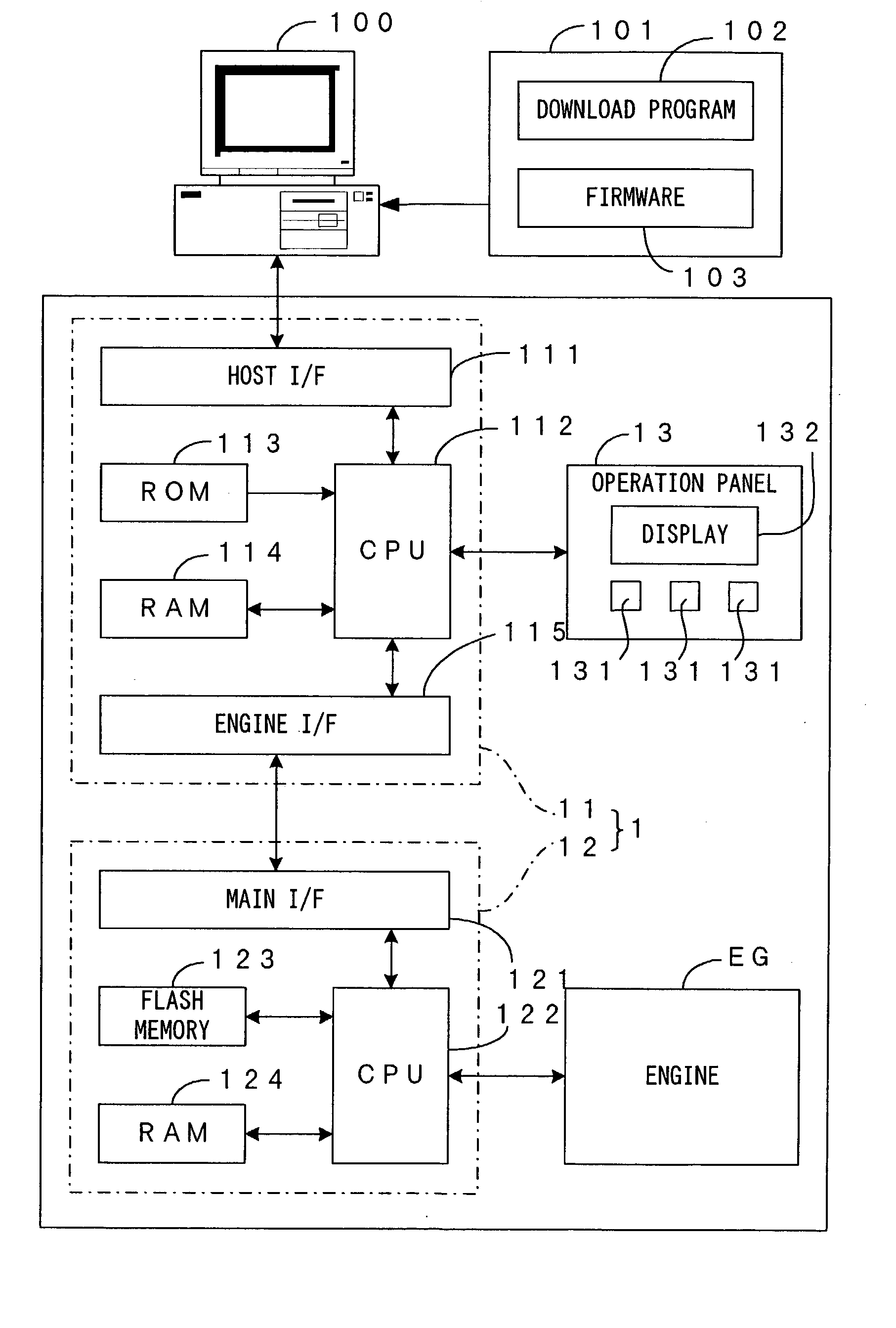
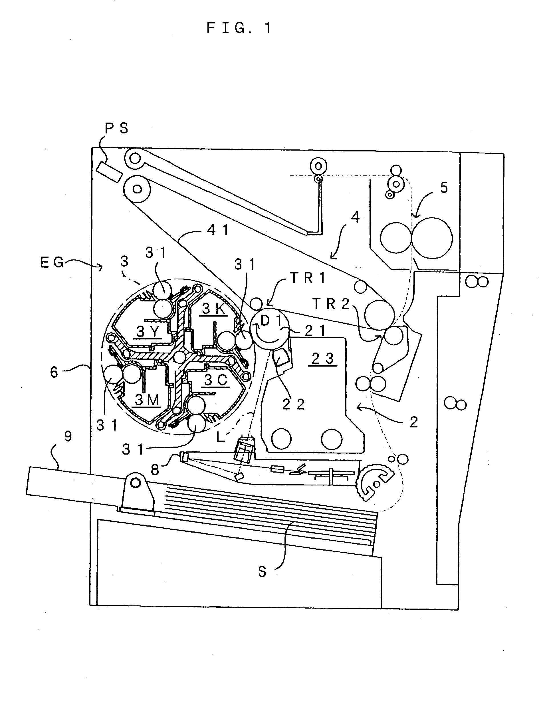
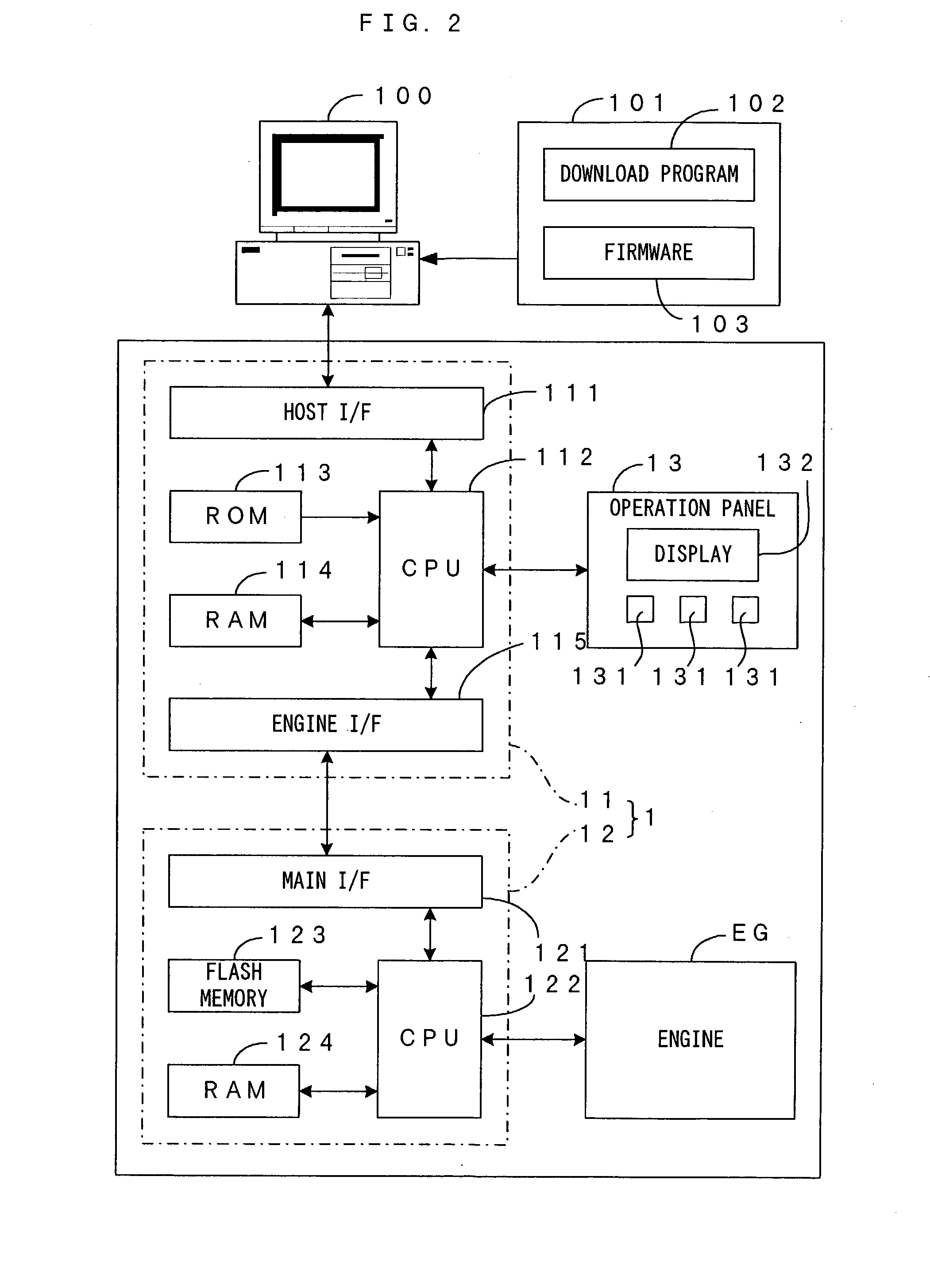
[0037] FIG. 1 is a drawing which shows a first embodiment of the present invention. FIG. 2 is a block diagram which shows an electric structure of an image forming apparatus which is shown in FIG. 1. This image forming apparatus is an apparatus which superposes toner in four colors of yellow (Y), magenta (M), cyan (C) and black (K) and accordingly formes a full-color image, or uses only toner in black (K) and accordingly formes a monochrome image. In this image forming apparatus, an image signal is fed to a main controller 11 of a control unit 1 from an external apparatus such as a host computer 100. The main controller 11 analyzes this image signal, performs various types of image processing, and then supplies the resulting image-processed signal to an engine controller 12. The engine controller 12 controls respective portions of an engine EG of the image forming apparatus based on firmware stored in a flash memory 123. The engine EG forms an image corresp...

second embodiment

[0071] B. Second Embodiment

[0072] FIG. 5 is a drawing which shows a second embodiment of the present invention. In this information processing system, as shown in FIG. 5, a host computer 300 and a printer 200 are connected for mutual communications with each other.

[0073] The host computer 300 corresponds to a "host apparatus" of the present invention. The host computer 300 sends various types of commands, bitmapped image data and the like to the printer 200, so that the printer 200 is controlled and prints a desired image. More particularly, the host computer 300 comprises: a CPU 301 which serves as a central processor; a ROM 302 in which a starter program for the host computer 300 and the like are stored; a RAM 303 in which a calculation result, data and the like are stored; and a hard disk 304 which stores a program, various types of data and the like which make the host computer 300 carry out a printer driver function, a print monitor function, etc.

[0074] The program inside the h...

third embodiment

[0097] C. Third Embodiment

[0098] By the way, while the first embodiment described above aims at improving the efficiency of rewriting of firmware by means of switching of the master and the slave. On the other hand, a third embodiment improves the efficiency through restriction of the types of commands which can be used in the rewrite mode. An image forming apparatus according to the third embodiment will now be described with a main emphasis on differences of the third embodiment from the first embodiment. The same structures will be denoted at the same reference symbols as those used in the first embodiment and will not be described again.

[0099] The ROM 113 stores a program for the main controller 11 in advance. As the CPU 112 and a logic circuit (not shown) operate in accordance with the program, the received image signal is processed through various types of image processing. That is, receiving the image signal from the host computer 100, the main controller 11 converts RGB data...


PUM


Abstract

A main controller sends a "rewrite mode" command to an engine controller. Receiving the command, the engine controller 12 sends a "roger" status. This switches the mode from a print mode to a rewrite mode. In the rewrite mode, the engine controller 12 serves as a master and the main controller 11 serves as a slave, a communication which is necessary for rewriting of firmware takes place between the two, and the firmware is rewritten.

Description

[0001] 1. Field of the Invention[0002] The present invention relates to a technique for rewriting firmware which is stored in a memory. To be more specific, the present invention is applicable to an image forming apparatus in which a main controller is connected for mutual communications with an engine controller which comprises a rewritable memory which stores firmware. The present invention is applicable also to an information processing system in which a host apparatus is connected for mutual communications with an image forming apparatus which comprises a rewritable memory which stores firmware. Further, the present invention is applicable to a rewriting method, a rewriting program and a recording medium for rewriting firmware which is stored in a memory of an engine controller or the like which is disposed in an image forming apparatus.[0003] 2. Description of the Related Art[0004] Known as an image forming apparatus such as a printer, a copier machine and a facsimile machine i...

Claims


Application Information

Patent Timeline
Patent Type & Authority Applications(United States)
IPC IPC(8): G06F9/445
CPCG06F8/65
Inventor SUGITA, TAKATOSHI
Owner SEIKO EPSON CORP
Learn More