
Worm wheel and method of manufacturing the same

Inactive Publication Date: 2005-11-10
NSK LTD +1
View PDF0 Cites 16 Cited by
  • Summary
  • Abstract
  • Description
  • Claims
  • Application Information

AI Technical Summary

Benefits of technology

[0009] The present invention has been made in view of the above-described circumstances. An object of the present invention is to provide a worm wheel in which coaxiality of a synthetic resin gear ring and a metal worm wheel element is enhanced and to provide a method for manufacturing such a worm wheel.
[0015] According to the present invention, positioning of the metal worm wheel in the mold can be effected with a high degree of accuracy, and coaxiality of the metal worm wheel element and the synthetic resin gear ring can be enhanced.

Problems solved by technology

However, this type of power steering apparatus suffers from a large drive loss (as much as about several horsepower to ten horsepower at the maximum load) due to continuous driving of the hydraulic pump, and therefore, a considerable decrease in gas mileage is inevitable in, for example, light automobiles with a small engine displacement.

Method used


Image

  • Worm wheel and method of manufacturing the same
  • Worm wheel and method of manufacturing the same
  • Worm wheel and method of manufacturing the same

Examples


Embodiment Construction

[0026] In the following, embodiments of the present invention will be described with reference to the drawings.

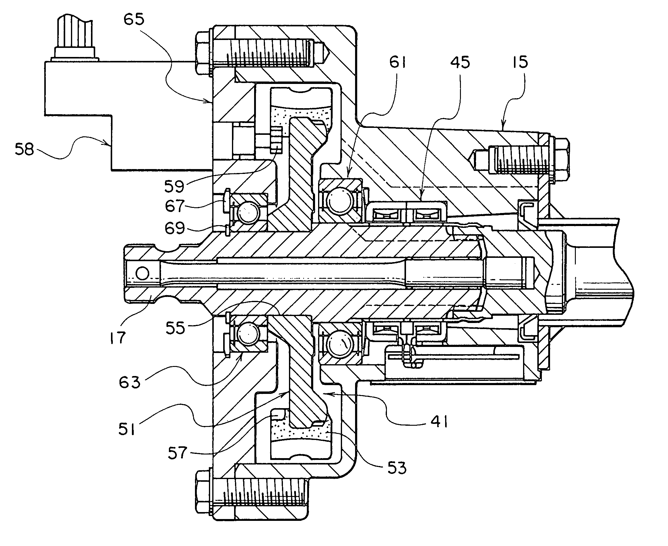
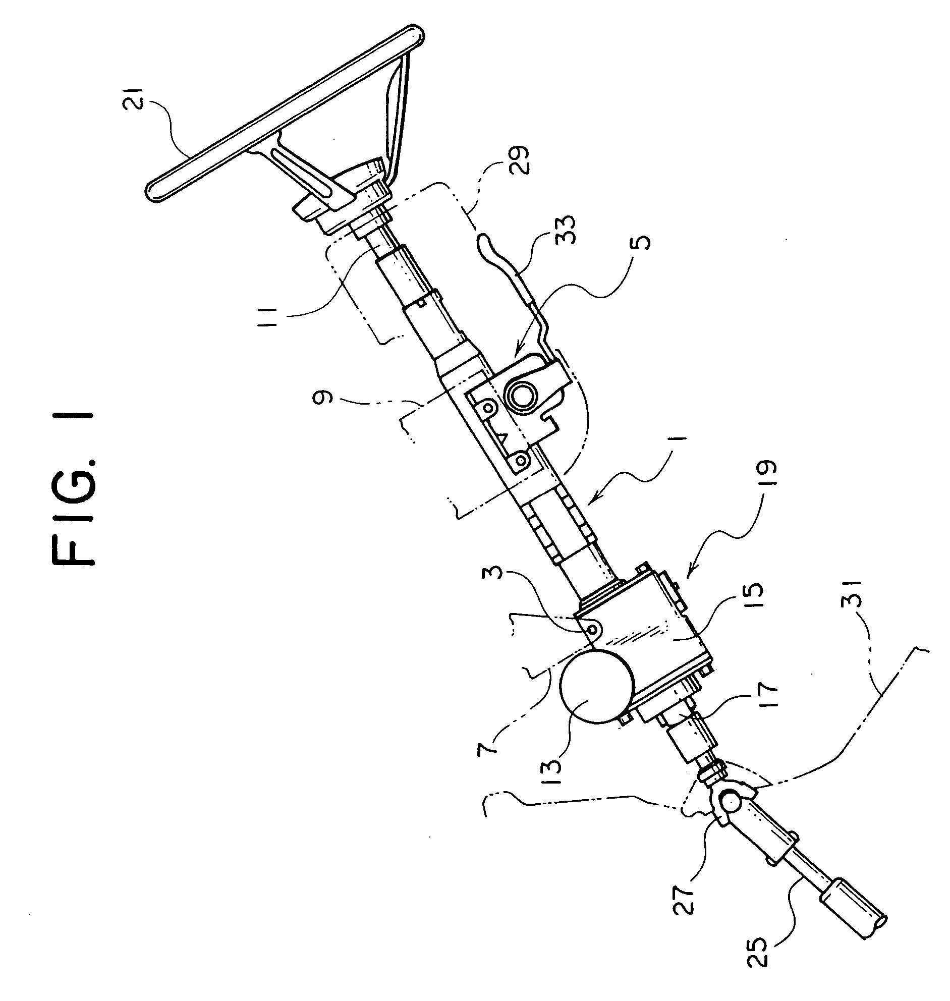
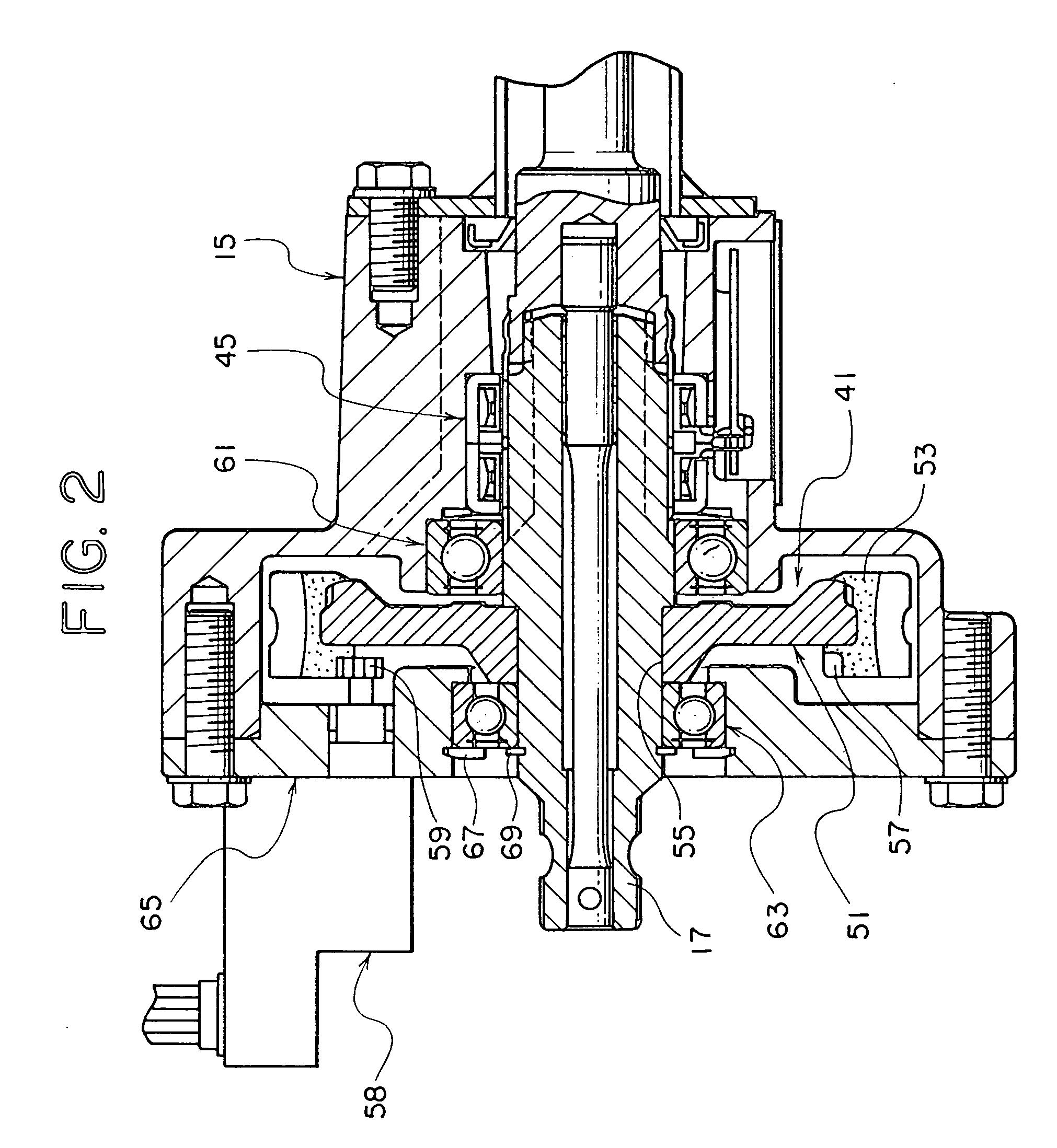
[0027]FIG. 1 is a side view showing the cabin side portion of a steering apparatus according to the first embodiment. In this drawing, reference numeral 1 designates a steering column. The steering column 1 is fixed to structural members 7 and 9 of a vehicle body by means of a pivot pin 3 and a tilt adjustment mechanism 5 respectively. Inside the steering column 1, a steering upper shaft 11 is rotatably supported, and an electric assist mechanism 19 composed of an electric motor 13, a gear housing 15 and output shaft 17 etc. is integrally formed on the steering column 1.

[0028] A steering wheel 21 is attached to the rear end of the steering upper shaft 11. When a driver turns the steering wheel 21, the rotational force is amplified by the electric assist mechanism 19 and transmitted to the output shaft 17. As shown in FIG. 1, a lower steering shaft 25 is connected to the f...


PUM

PropertyMeasurementUnit
Pressureaaaaaaaaaa
Circumferenceaaaaaaaaaa

Abstract

In a worm wheel (41) and a method of manufacturing the same, the worm wheel has a metal worm wheel element (51) in which an axial bore (55) is formed at a rotational center and a synthetic resin gear ring (53) attached on the outer circumference of the worm wheel element, and a centering guide portion (77) that is coaxial with the axial bore (55) is formed on one surface of the metal worm wheel element (51).

Description

TECHNICAL FIELD [0001] The present invention relates to a worm wheel having a worm wheel element made of a metal and a gear ring made of a synthetic resin and a method of manufacturing the same. More particularly, the present invention relates to a technology for improving coaxiality of the synthetic resin gear ring and the metal worm wheel element. BACKGROUND ART [0002] So-called power steering apparatuses that provide steering assist using an external drive source are widely used in steering systems for automobiles. [0003] Conventionally, hydraulic vane pumps are commonly used as the power source for power steering apparatuses. In most cases, the hydraulic pump is driven by an engine. However, this type of power steering apparatus suffers from a large drive loss (as much as about several horsepower to ten horsepower at the maximum load) due to continuous driving of the hydraulic pump, and therefore, a considerable decrease in gas mileage is inevitable in, for example, light automo...

Claims


Application Information

Patent Timeline
IPC IPC(8): B29C45/14F16H55/22
CPCB29C45/14065B29C45/1459B29C2045/14139Y10T74/19828B29L2015/003B29L2031/7754F16H55/22B29K2705/00
Inventor YAMAMOTO, TAKESHIIWANO, TOSHIYUKI
Owner NSK LTD
Features
  • Generate Ideas
  • Intellectual Property
  • Life Sciences
  • Materials
  • Tech Scout
  • Unparalleled Data Quality
  • Higher Quality Content
  • 60% Fewer Hallucinations
Learn More