Electronic throttle control with hysteresis device

Active Publication Date: 2005-11-10
KSR IP HLDG
View PDF12 Cites 33 Cited by
  • Summary
  • Abstract
  • Description
  • Claims
  • Application Information

AI Technical Summary

Benefits of technology

[0010] One advantage of the present invention is that an electronically controlled pedal assembly is provided that includes a hysteresis device to simulate the resistance to depression of the pedal. Another advantage of the present invention is that the hysteresis device for the electronically controlled pedal is simpler in design than previous designs, to enhance packageability within the interior environment of the vehicle. Still another advantage of the present invention is that the hysteresis device is cost-effective to manufacture. A further advantage of the present invention is that an electronically c

Problems solved by technology

However, since the pedal arm is not attached to a mechanical device, such as a rod or cable, there is no resistance to depression of the pedal, and the pedal returns to a nominal position quicker than with a mechanical system.
Without a predetermined amount of hysteresis in the pedal, the driver may experience increased foot fatigue

Method used


Image

  • Electronic throttle control with hysteresis device
  • Electronic throttle control with hysteresis device
  • Electronic throttle control with hysteresis device

Examples


Example

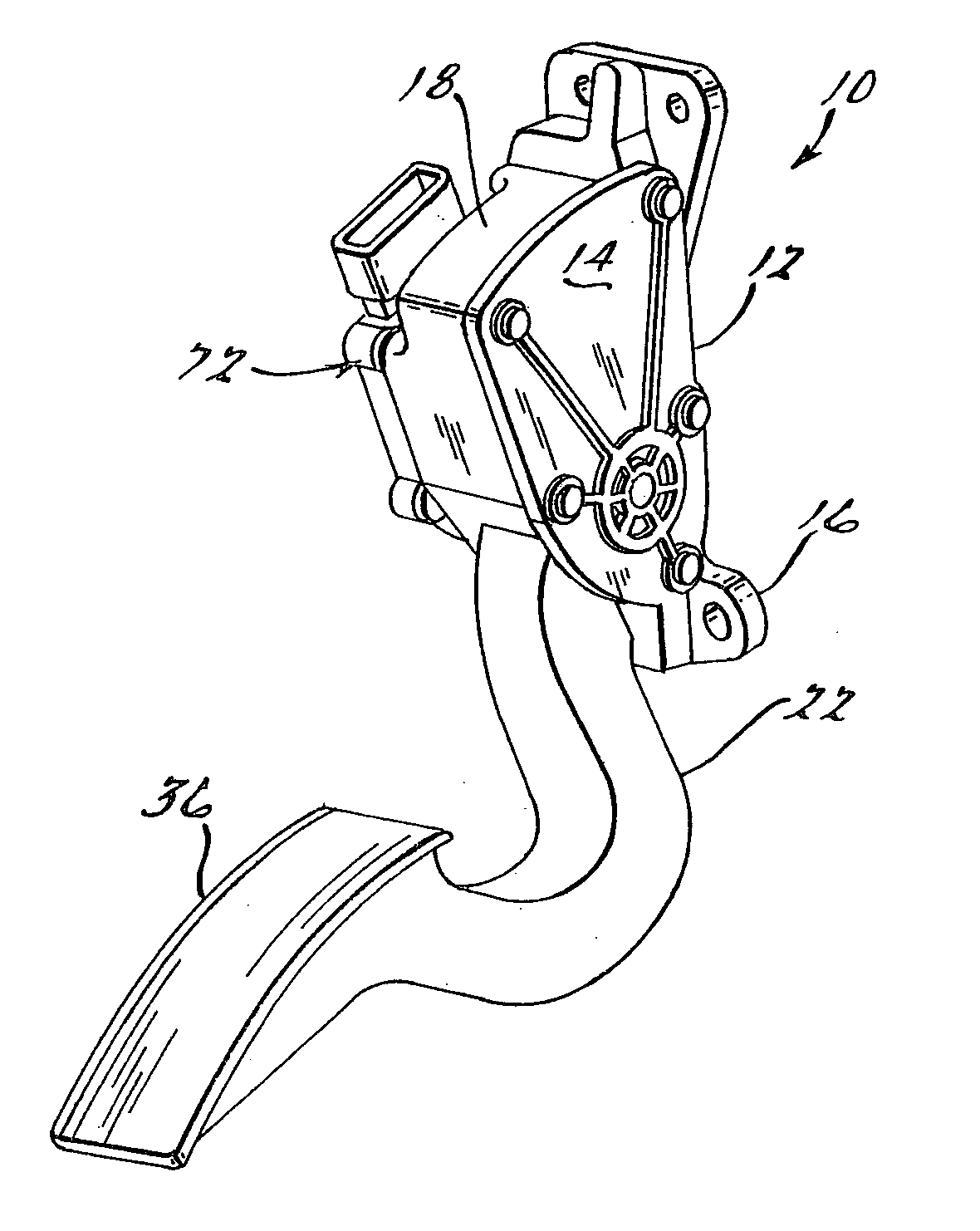
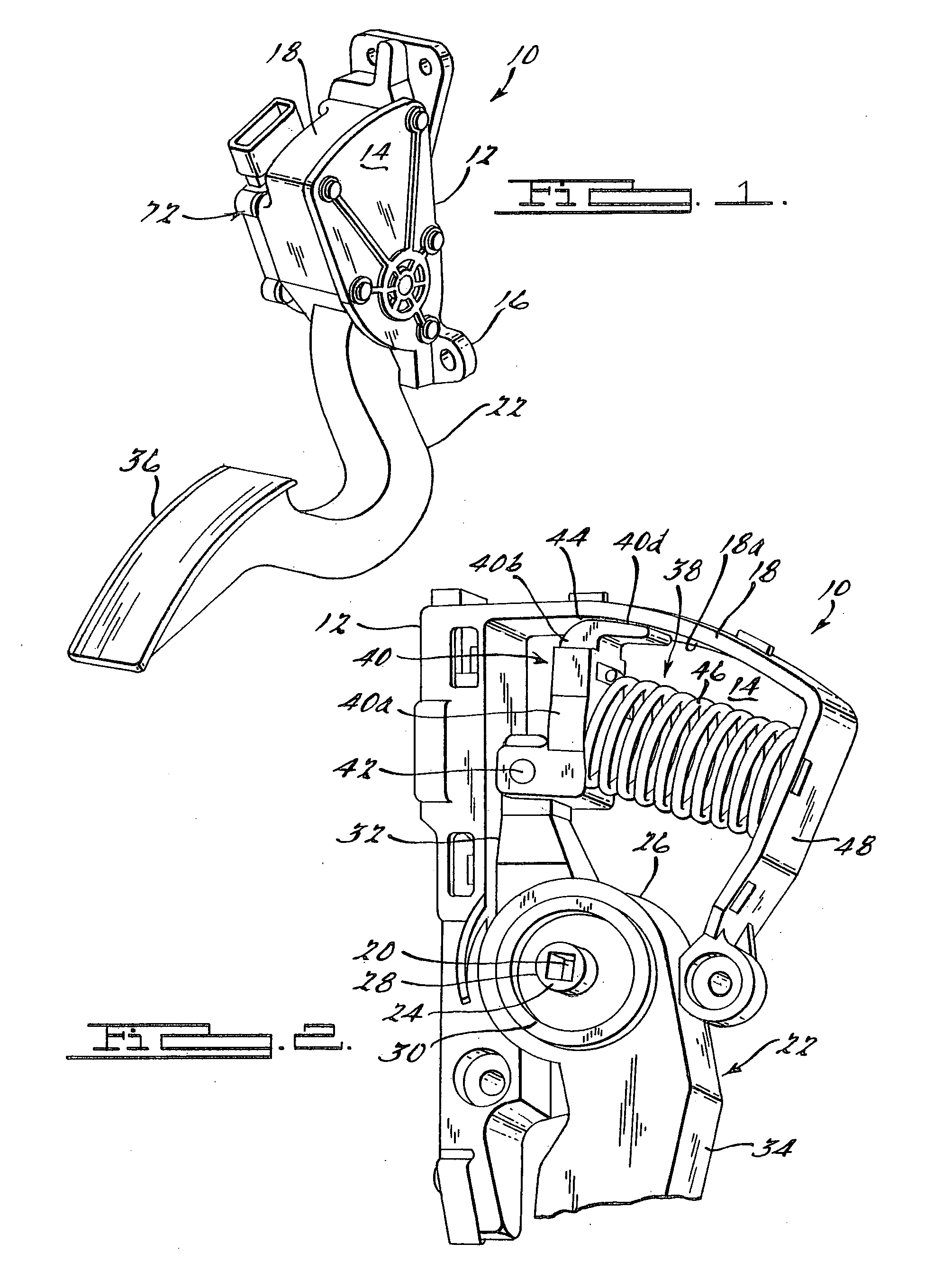
[0023] Referring to FIGS. 1 and 2, an electronically controlled pedal assembly is illustrated. It should be appreciated that in this example the electronically controlled pedal is a throttle pedal, although other types of pedals are contemplated, such as brake pedal, a clutch pedal, or the like.

[0024] The electronic throttle control pedal assembly 10 of this example transmits a signal from the driver to a throttle controller (not shown) regarding movement of the vehicle. The pedal assembly 10 includes a housing 12 having a front wall 14 with tabs 16 for mounting the pedal assembly 10 to a vehicle (not shown). Extending from an edge of the front wall 14 at the top of the housing is friction wall 18 having an arcuate shape and a radius of curvature centered at a pedal arm pivot point 20. The pedal assembly 10 includes a pedal arm 22 rotatably supported by a mounting means shown at 24. The mounting means 24 rotatably supports the pedal arm 22, so that the pedal arm 22 rotates about th...


PUM


Abstract

An electronically controlled pedal assembly with hysteresis includes a housing having a front wall and an arcuate friction wall having a radius of curvature centered on a pedal arm pivot point and extending from an edge of the front wall. The pedal assembly also includes a pedal arm rotatably supported at the pedal arm pivot point by a mounting means operatively connected to the housing, and a hysteresis generating means pivotally mounted to the pedal arm. The pedal assembly further includes a spring positioned between the housing and the hysteresis generating means, such that the spring biases the hysteresis generating means against the housing, so that depression of the pedal arm compresses the spring while generating an increasing frictional hysteresis force between the arcuate friction wall and the hysteresis generating means that is translated back through the pedal arm, and release of the pedal arm reduces the frictional hysteresis force.

Description

RELATED APPLICATIONS [0001] This application claims priority of U.S. Provisional Patent Application 60 / 396,623 filed Jul. 17, 2002, entitled “Electronic Control With Hysteresis Device” (pending), and 60 / 413,504 filed Sep. 25, 2002 entitled “Induction Sensor for Pedal with Hysteresis Device” (pending) both of which are incorporated herein by reference.BACKGROUND OF THE INVENTION [0002] 1. Field of the Invention [0003] The present invention relates generally to electronic controls for vehicles, and more particularly, to an electronically controlled pedal with a hysteresis device. [0004] 2. Description of the Related Art [0005] Vehicles, and in particular automotive vehicles, utilize a foot-operated device, such as a brake pedal or a throttle control pedal, also referred to as an accelerator pedal, to control the movement of the vehicle. Conventional brake systems include a brake pedal for transmitting a braking force from the vehicle operator to the wheels of the vehicle. Similarly, c...

Claims


Application Information

Patent Timeline
IPC IPC(8): F02DF02D1/00G05G1/38G05G5/03
CPCG05G1/38G05G1/44Y10T74/20888Y10T74/20528Y10T74/20534G05G5/03
Inventor WILLEMSEN, LARRY G.O'NEILL, DANMISHCHENKO, PETERSOTEROS, ROBKOCWICH, GREG
Owner KSR IP HLDG
Why Eureka
Try Eureka