Energy-releasing apparatus for energizing and covibrating fuel molecules and arranging reactant molecules

a technology of energy-releasing apparatus and fuel molecules, which is applied in the direction of combustion engine, combustion-air/fuel-air treatment, charge feed systems, etc., can solve the problems of not being able to fully energize all, the alkylate of the fuel cannot be fully burned in the combustion chamber, and the alkylate of the fuel cannot be hardly burned to an optimal extent, so as to facilitate the burning reaction and maximize the output power per unit fuel

Inactive Publication Date: 2005-11-10
JEWEL JAR INT
View PDF8 Cites 2 Cited by
  • Summary
  • Abstract
  • Description
  • Claims
  • Application Information

AI Technical Summary

Benefits of technology

[0004] It is therefore a primary object of the present invention to provide an energy-releasing apparatus for energizing and covibrating fuel molecules and arranging reactant molecules. The energy-releasing apparatus can generate a left-handed force field for arranging the molecules of all the reactants participating in the burning reaction. Accordingly, the fuel molecules are energized to facilitate burning reaction and achieve a complete reaction. Therefore, the output power per unit fuel can be maximized.

Problems solved by technology

However, in fact, the alkylate of the fuel can fully burn in the combustion chamber only in condition of sufficient oxygen and proper ignition.
The above conventional magnetic fuel-saving apparatus simply applies a magnetic force to the fuel, while failing to energize all the reactants.
Therefore, the alkylate of the fuel can hardly burn to an optimal extent.

Method used


Image

  • Energy-releasing apparatus for energizing and covibrating fuel molecules and arranging reactant molecules
  • Energy-releasing apparatus for energizing and covibrating fuel molecules and arranging reactant molecules
  • Energy-releasing apparatus for energizing and covibrating fuel molecules and arranging reactant molecules

Examples


Embodiment Construction

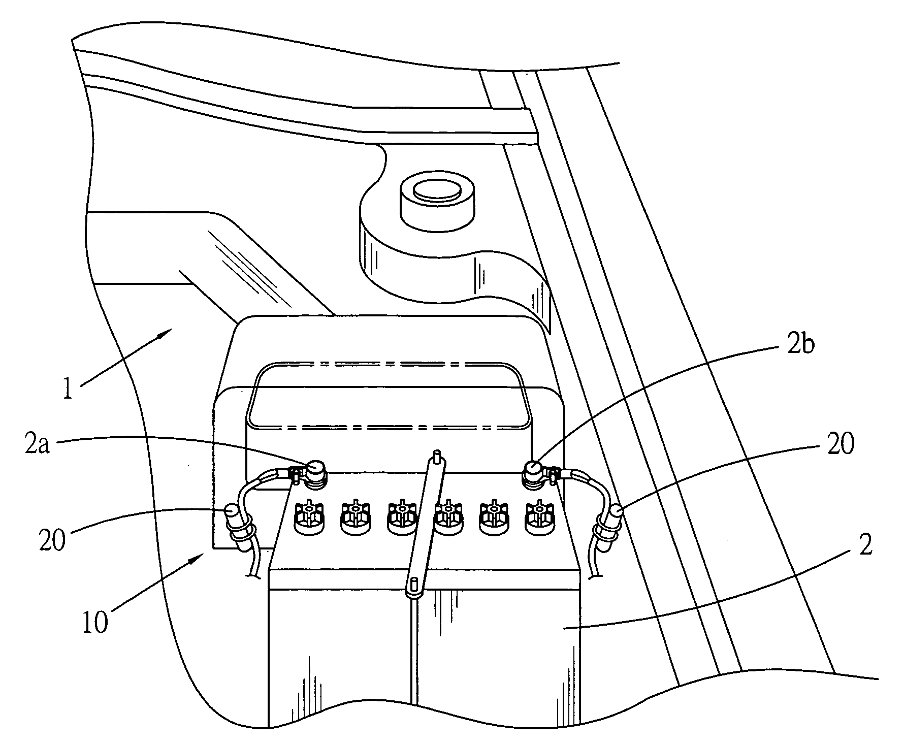
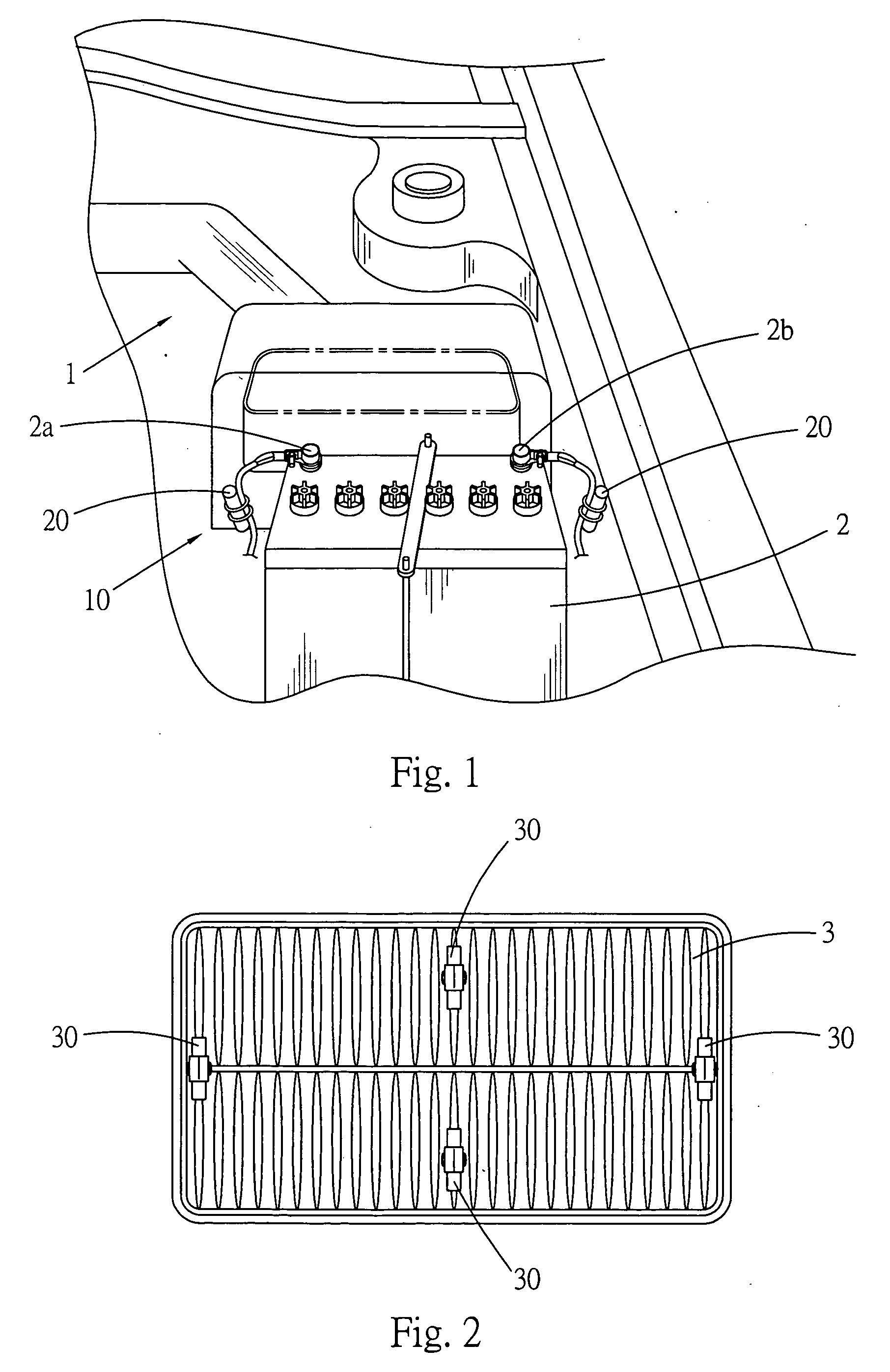
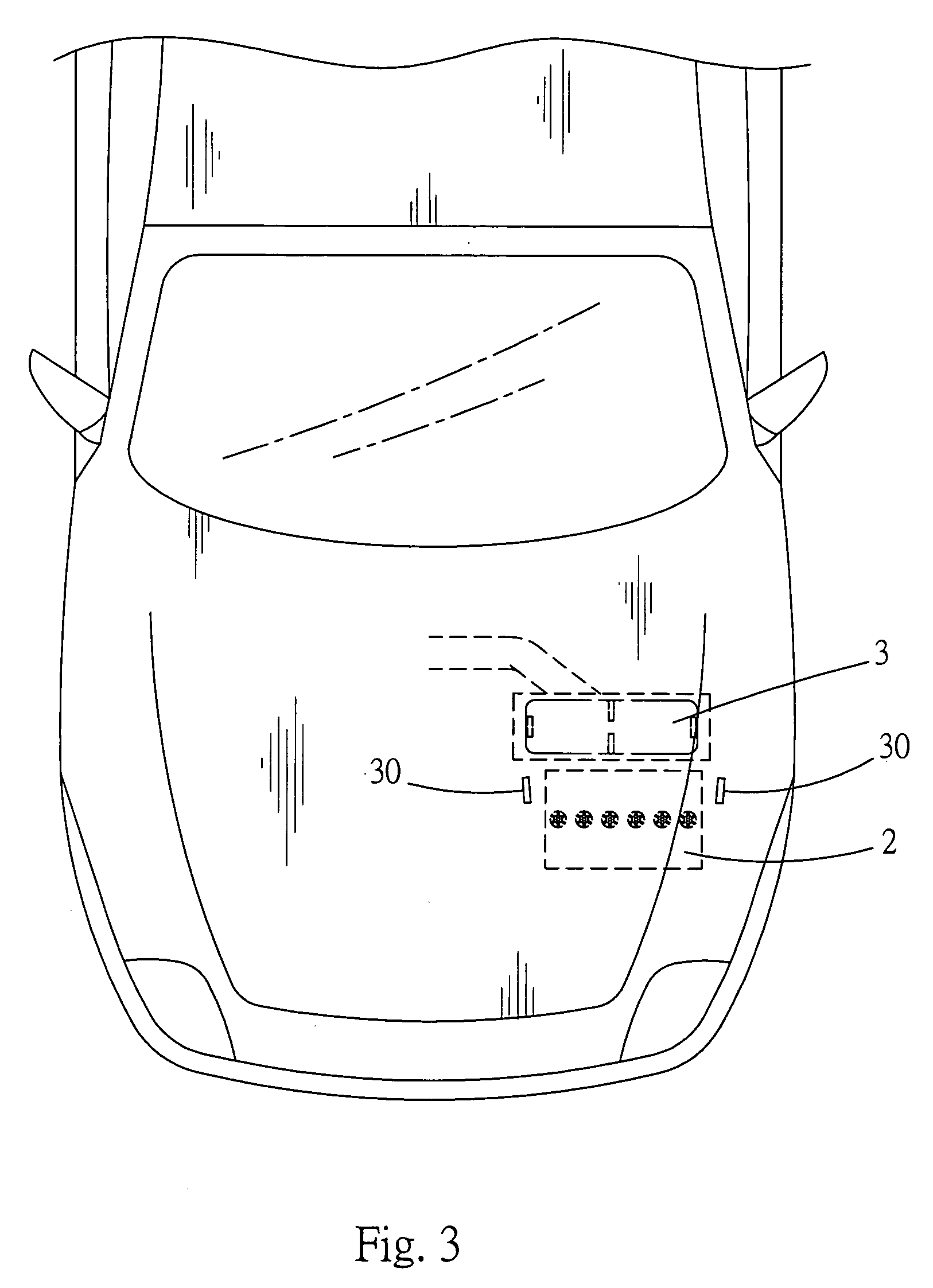
[0010] Please refer to FIGS. 1 to 3. The energy-releasing apparatus 10 for energizing and covibrating fuel molecules and arranging reactant molecules of the present invention is installed in the engine compartment 1 of a vehicle. The energy-releasing apparatus 10 is composed of two first energy-releasing sections 20 and four second energy-releasing sections 30.

[0011] The two first energy-releasing sections 20 are respectively disposed near the positive and negative electrodes 2a, 2b of the battery 2 in the engine compartment 1. Substantially, in this embodiment, the first energy-releasing sections 20 are respectively tied on the leads of the positive and negative electrodes 2a, 2b with binding straps. The first energy-releasing sections 20 generate left-handed force field to respectively act on the electrons flowing between the positive and negative electrodes 2a, 2b so as to tidily arrange the electrons. Accordingly, when the fuel is ignited to burn in the combustion chamber, the ...


PUM


Abstract

An energy-releasing apparatus for energizing and covibrating fuel molecules and arranging reactant molecules. The energy-releasing apparatus is installed in a predetermined position in an engine compartment of a vehicle. The energy-releasing apparatus includes at least one first energy-releasing section disposed beside the electrodes of the battery in the engine compartment chamber and at least one second energy-releasing section disposed in the engine compartment beside the intake duct of the combustion chamber. The first and second energy-releasing sections generate left-handed force field to arrange the electrons or the battery and the gas molecules in the intake duct. The left-handed force field further energizes the alkylate molecules of the fuel entering the combustion, whereby the molecules of all the reactants participating in the burning reaction are uniformly arranged and activated so as to achieve a complete reaction.

Description

BACKGROUND OF THE INVENTION [0001] The present invention is related to an energy-releasing apparatus for energizing and covibrating fuel molecules and arranging reactant molecules. [0002] A conventional magnetic fuel-saving apparatus includes a magnetized metal body mounted around the fuel line of a vehicle. When the fuel goes through the magnetic field generated by the fuel-saving apparatus, a magnetic force is applied to the fuel to arrange the molecules of the fuel. Accordingly, the fuel can more fully react and burn in the combustion chamber so as to save fuel. [0003] However, in fact, the alkylate of the fuel can fully burn in the combustion chamber only in condition of sufficient oxygen and proper ignition. The above conventional magnetic fuel-saving apparatus simply applies a magnetic force to the fuel, while failing to energize all the reactants. Therefore, the alkylate of the fuel can hardly burn to an optimal extent. SUMMARY OF THE INVENTION [0004] It is therefore a primar...

Claims


Application Information

Patent Timeline
Patent Type & Authority Applications(United States)
IPC IPC(8): F02B51/00F02B51/04F02M7/24F02M27/04
CPCF02B51/04Y02T10/126F02M27/04Y02T10/12
Inventor LIAO, TZU-YUAN
Owner JEWEL JAR INT
Why Eureka
Try Eureka