Heat dissipation element for cooling electronic devices

a technology of heat dissipation element and electronic device, which is applied in the direction of indirect heat exchanger, laminated element, light and heating apparatus, etc., can solve the problems of significant challenges in the process of optimizing tcu performance, heat dissipation rate, and relatively low heat capacity of air, so as to maximize the amount of heat and dissipate increased amounts of heat

Inactive Publication Date: 2005-11-10
DELPHI TECH INC
View PDF13 Cites 34 Cited by
  • Summary
  • Abstract
  • Description
  • Claims
  • Application Information

AI Technical Summary

Benefits of technology

[0010] The subject invention provides a heat dissipation element for cooling an electronic device. The heat dissipation element includes a top surface and a bottom surface for mounting thereto an electronic device to be cooled. The top surface defines a heat dissipation area for dissipating heat from the electronic device. A plurality of heat transfer f

Problems solved by technology

However, these electronic devices are increasingly being miniaturized and designed to achieve increased computing speeds that generate heat up to 200 W/cm2.
However, air has a relatively low heat capacity.
This poses significant challenges to the process of optimizing the TCU performance.
However, none of these references discloses a cooling unit having a plurality of f

Method used


Image

  • Heat dissipation element for cooling electronic devices
  • Heat dissipation element for cooling electronic devices
  • Heat dissipation element for cooling electronic devices

Examples


Embodiment Construction

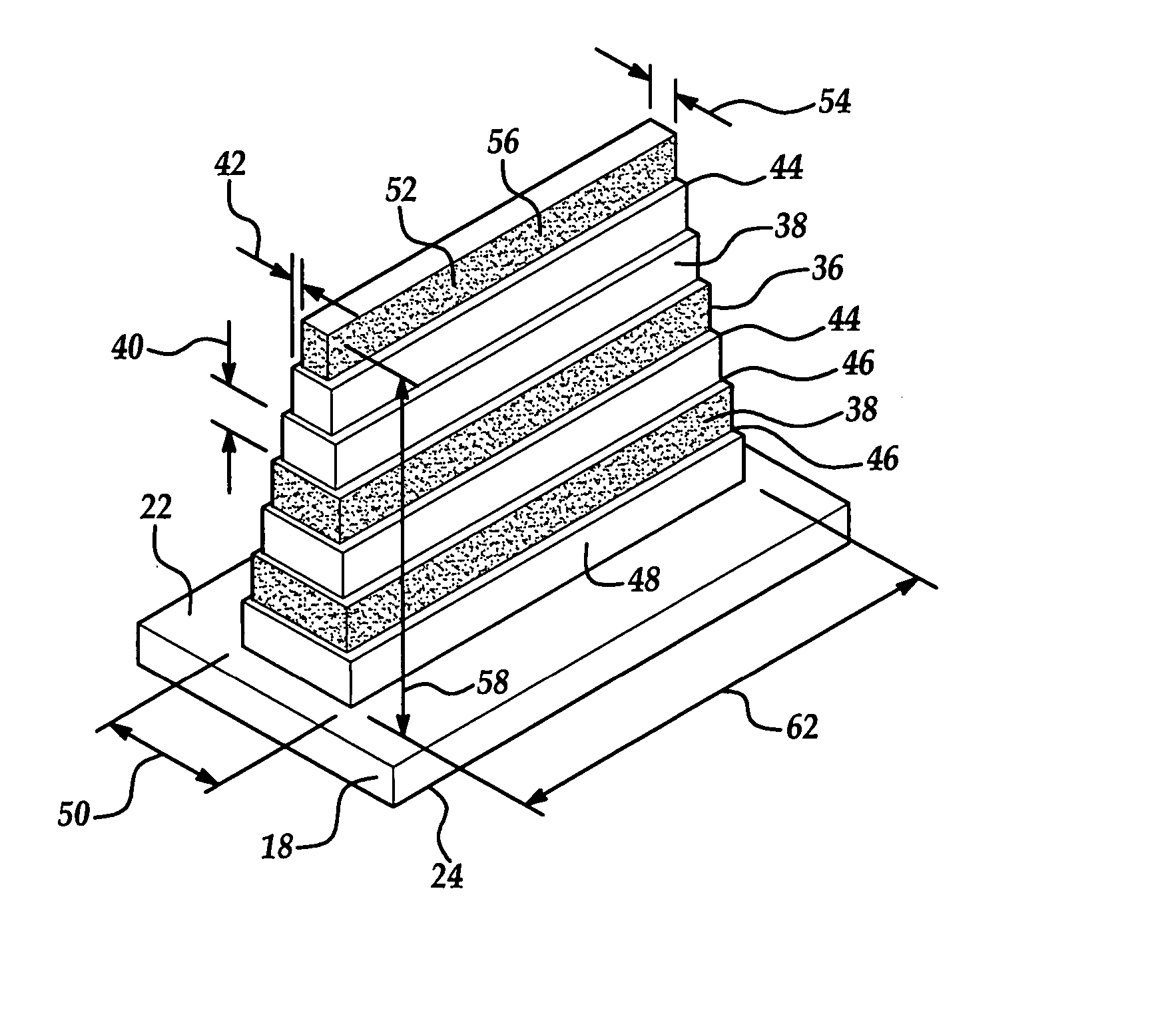
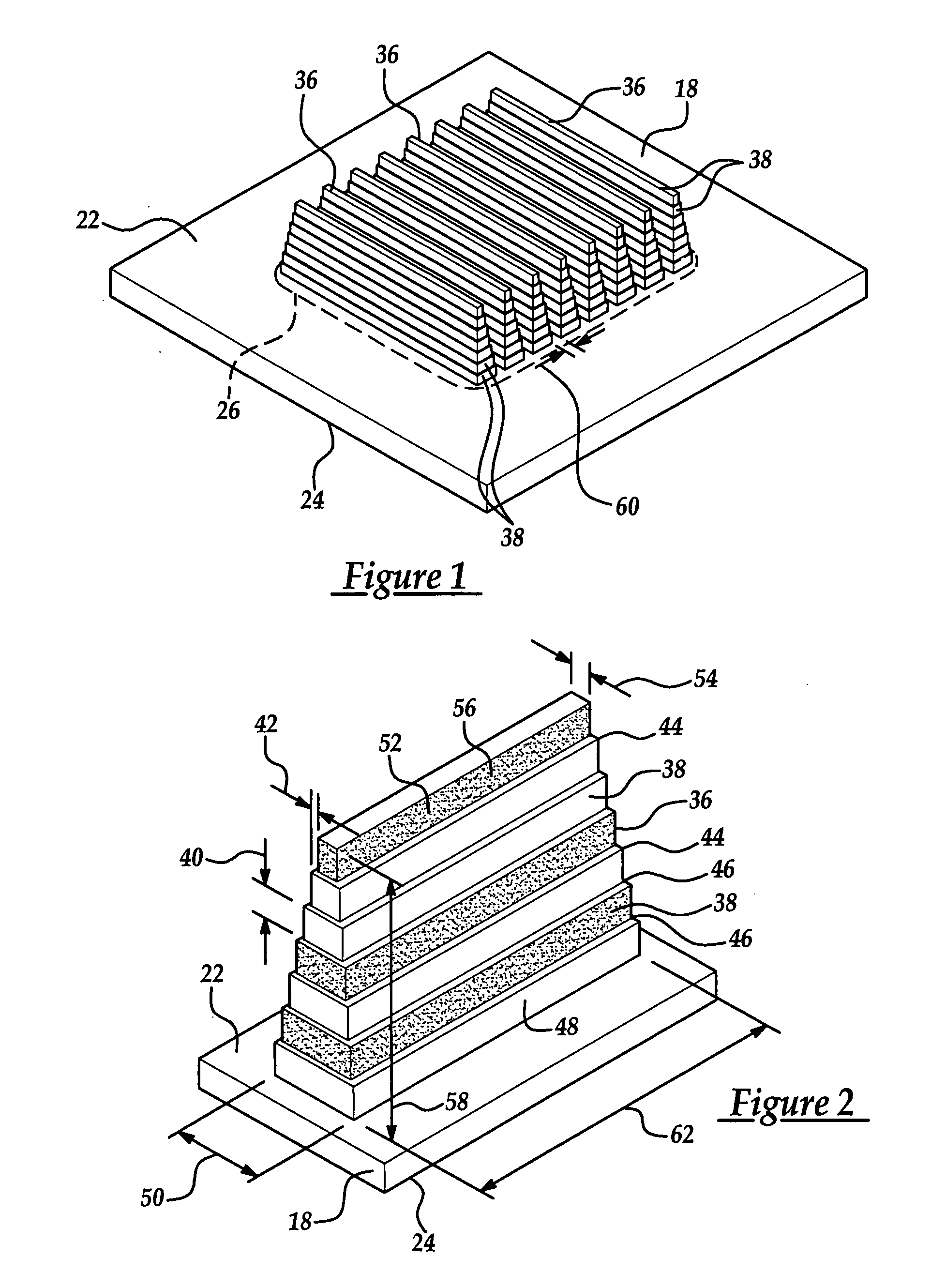
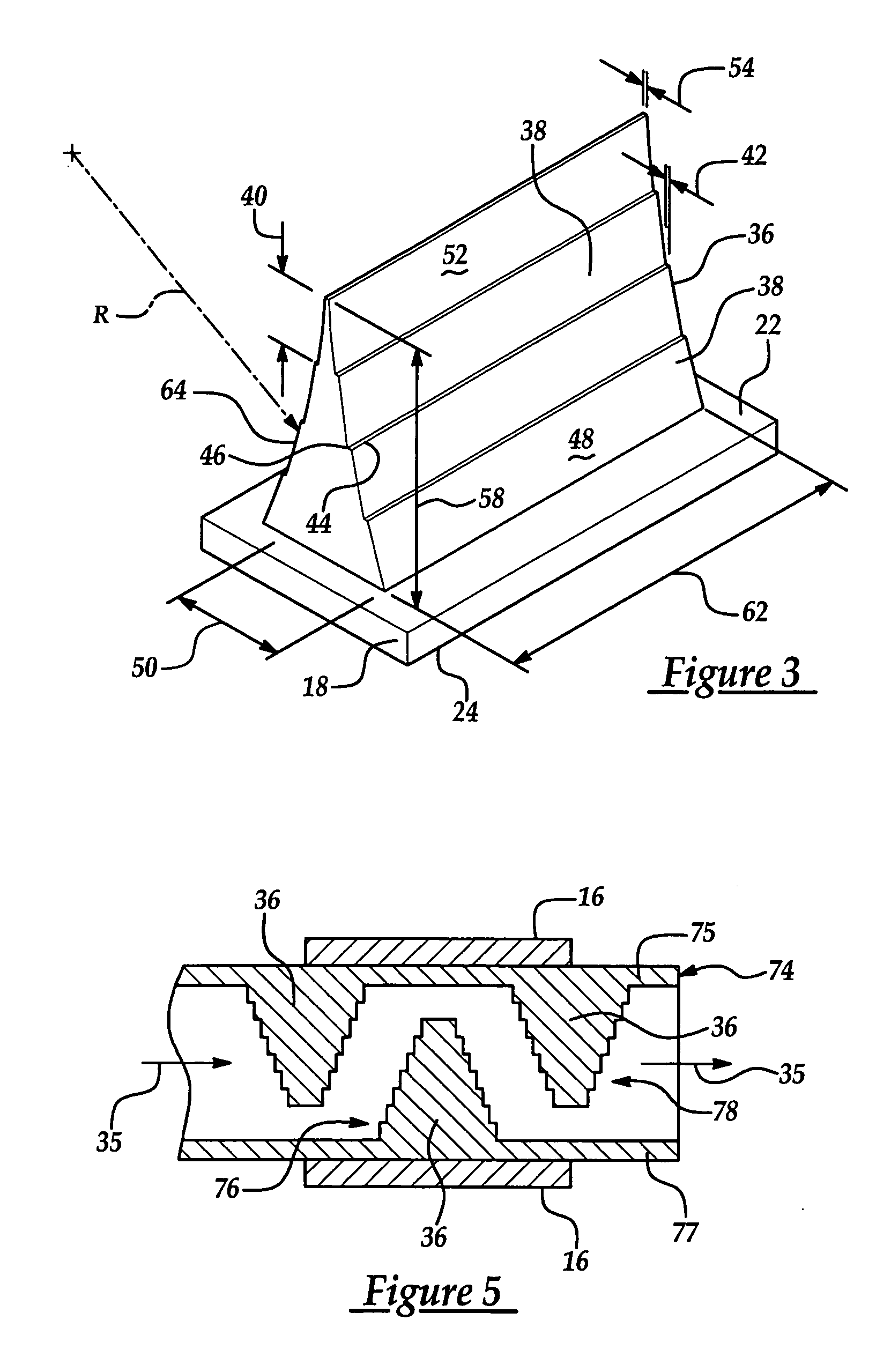
[0020] Referring to the Figures, wherein like numerals indicate like or corresponding parts throughout the several views, a heat dissipation element for cooling an electronic device 16 is shown generally at 18 in FIG. 1. The subject invention is particularly useful with electronic devices 16 (best shown in FIGS. 5 and 7) such as, but not limited to, computer chips, telecommunication chips, microprocessor assemblies, and the like. These electronic devices 16 are used in various systems (not shown), such as computer systems, telecommunication systems, and the like. The electronic devices 16 are preferably flexibly attached to the heat dissipation element 18. However, one skilled in the art may connect the electronic devices 16 by other methods without deviating from the subject invention.

[0021] The heat dissipation element 18 includes a top surface 22 and a bottom surface 24 for mounting thereto the electronic device 16 (FIGS. 4, 5, and 7) to be cooled. The top surface 22 defines a h...


PUM


Abstract

A heat dissipation element for cooling an electronic device is disclosed. The heat dissipation element has a top surface and a bottom surface for mounting the electronic device to be cooled thereto. The top surface defines a heat dissipation area for dissipating heat from the electronic device and a plurality of heat transfer fins project upwardly from the top surface and are coextensive with the heat dissipation area. Each of the heat transfer fins defines a plurality of steps having a rise and a run and each of the steps extend across the heat dissipation area for maximizing an amount of heat dissipated from the electronic device. The heat dissipation element is particularly useful in either one of a cold plate assembly used with a liquid cooled unit (LCU) or a boiler plate assembly used with a thermosiphon cooling unit (TCU).

Description

BACKGROUND OF THE INVENTION [0001] 1. Field of the Invention [0002] The subject invention relates to a heat dissipation element for cooling an electronic device, and more specifically to a heat dissipation element capable of dissipating an increased amount of generated heat from an electronic device. [0003] 2. Description of Related Art [0004] Research activities have focused on developing assemblies to efficiently dissipate heat from electronic devices that are highly concentrated heat sources, such as microprocessors and computer chips. These electronic devices typically have power densities in the range of about 5 to 35 W / cm2 and relatively small available space for placement of fans, heat exchangers, heat sink assemblies and the like. However, these electronic devices are increasingly being miniaturized and designed to achieve increased computing speeds that generate heat up to 200 W / cm2. [0005] Heat exchangers and heat sink assemblies have been used that apply natural or forced...

Claims


Application Information

Patent Timeline
IPC IPC(8): F28D15/02F28F3/04F28F7/00F28F13/00
CPCF28D15/0233F28F13/00F28F3/04
Inventor BHATTI, MOHINDER SINGHREYZIN, ILYAGHOSH, DEBASHISJOSHI, SHRIKANT MUKUND
Owner DELPHI TECH INC
Why Eureka
Try Eureka